How to Install OpenShift on Bare Metal: Step-by-Step Guide


OpenShift runs best on bare metal servers because it can use the hardware directly without extra layers slowing things down. This ensures better performance, steady networking, and more control than running it on shared or virtualized environments.
This guide demonstrates how to install OpenShift 4.19.11 on bare metal using the assisted installer. We cover the essentials before the cluster comes online, preparing the servers, planning the network, setting up the admin workstation, and adding the required Red Hat pull secret.
For the environment, we are using bare metal servers from Cherry Servers. This provides direct access to identical machines on the same private network, which is precisely what OpenShift needs for a stable control plane.
#Prerequisites
Before we start the installation, there are a few things we need to have in place. These make sure the setup goes smoothly.
- Red Hat account: You need a Red Hat developer account to access the Assisted Installer and generate a pull secret.
- Pull secret: Create and download a pull secret from the console. It is required for pulling container images during installation.
- SSH key pair: Create an SSH key. We will attach it to each server and to the cluster. This allows secure, passwordless access later when you connect to the nodes.
- Public and private networking: Each server needs a public IP address with outbound Internet access. The Discovery ISO must reach OpenShift’s API and Red Hat container registries. Also, all servers must share a private VLAN for the cluster network. In our case, this was VLAN 2832 (10.182.70.0/24).
- Switch configuration: The network interfaces must support VLAN tagging (802.1Q). Each server has two physical NICs (eno1 and eno2), but for this guide, we use only eno1. The public uplink runs untagged on eno1, while the private VLAN is carried as a tagged VLAN (eno1.2832) on the same interface. Cherry Servers' switches support this configuration by default.
- OpenShift CLI (oc): You will need it after the cluster comes up to run health checks and manage the cluster. The latest binaries are available from Red Hat’s official site.
- Java and iKVM viewer: The BMC uses an IPMI-based KVM console that requires Java Runtime Environment 8 or newer, or a JNLP launcher like OpenWebStart or IcedTea-Web.
#Step 1: Deploy 3 bare metal servers
We are using Cherry Servers for this guide. Any provider with VLAN support could work, but we get VLANs and public uplinks from Cherry Servers.
#Choose a server type
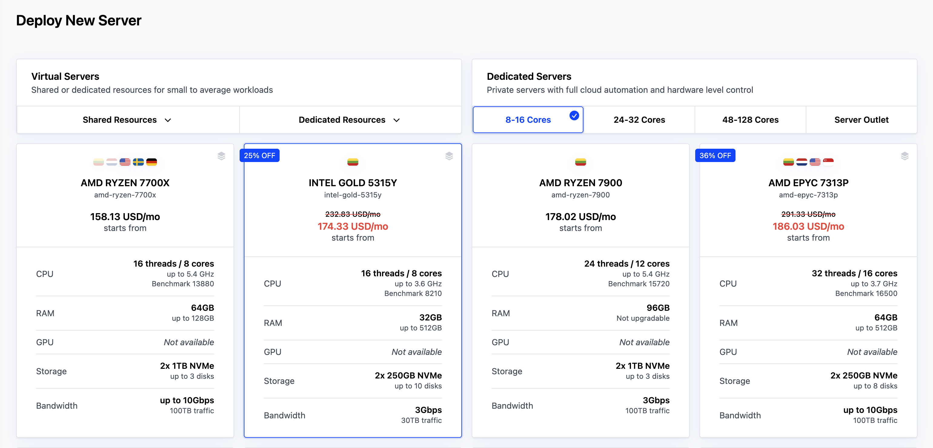
From the server catalog, pick a server that meets the OpenShift minimums and gives us a little extra headroom. We are using the Intel Gold 5315Y for this guide. It comes with:
- 8 cores/16 threads
- 64 GB RAM
- Two 1TB NVMe disks
- 3 Gbps bandwidth
This is more than enough for a compact three-node control-plane cluster. We could get by with the minimum (4 cores, 16 GB RAM, 100 GB SSD per node), but extra headroom keeps the cluster from choking later.
When deploying multiple servers for OpenShift, order all three servers in a single batch. Cherry Servers' private VLANs are switch-specific and do not span across different physical switches.
If servers are provisioned separately or assigned to different switches, they cannot communicate over the private VLAN, even if they are configured with addresses in the same subnet. Ordering all servers simultaneously ensures they are placed on the same physical infrastructure.
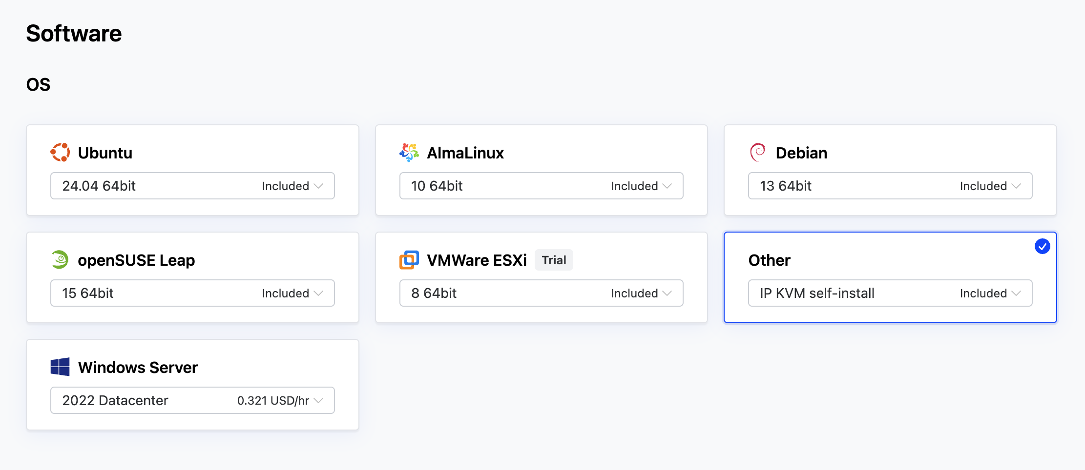
#Set the OS option
In the OS (Operating System) section, select Other IP KVM self-install. This is important because it allows us to manually mount the OpenShift Discovery ISO during installation.
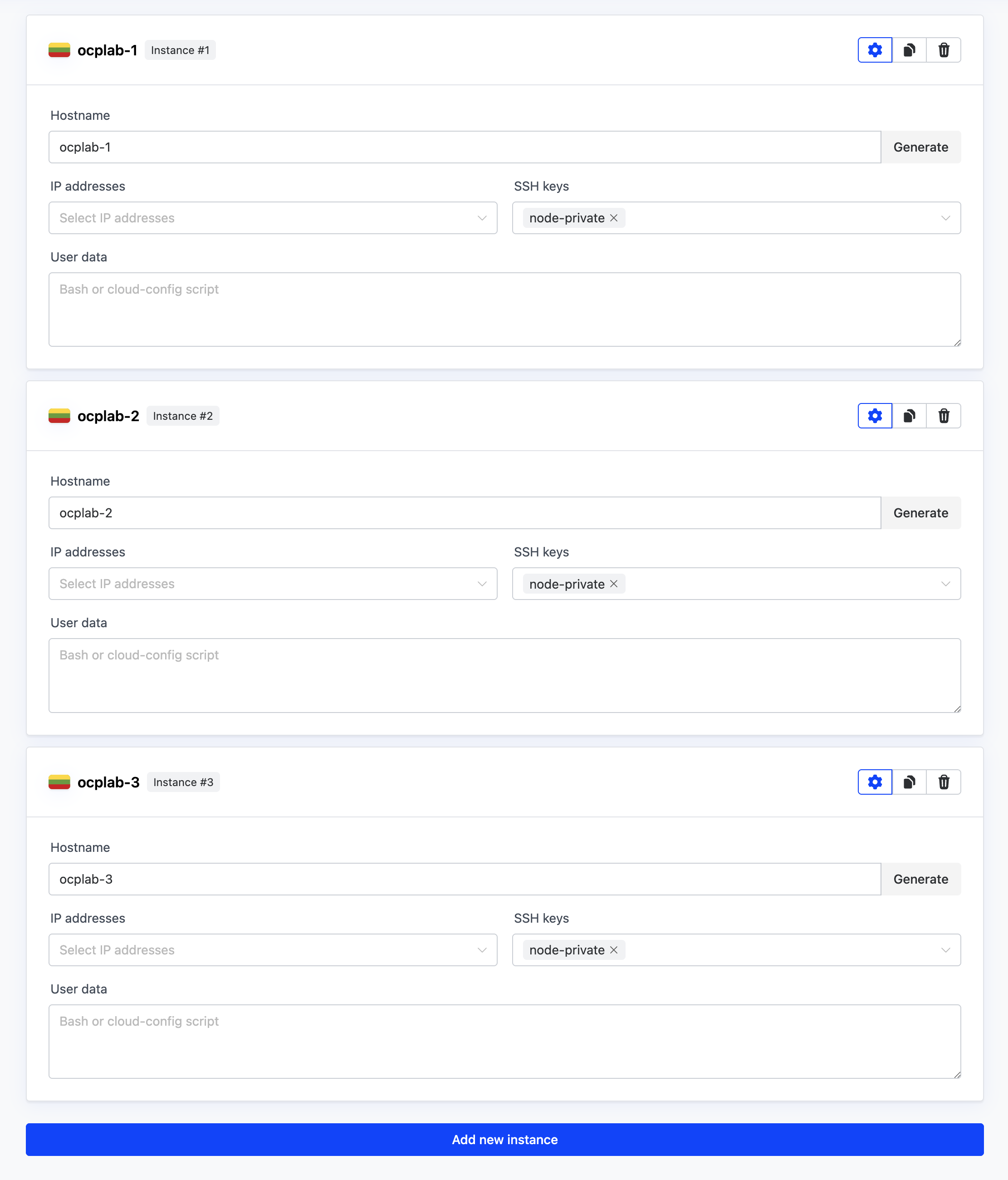
#Name the servers
Next, add 3 instances in the Instances section. Give each instance a simple name that matches the cluster. For this guide, we use ocplab-1, ocplab-2, and ocplab-3. Then, add your SSH key in the SSH keys section.
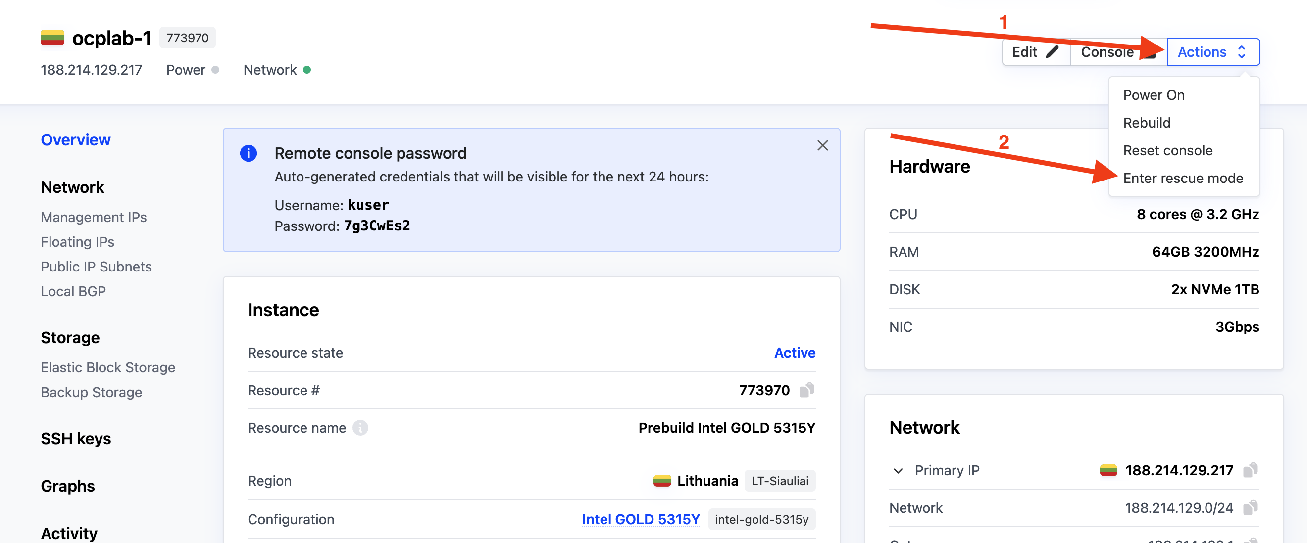
#Step 2: Collect NIC MAC addresses
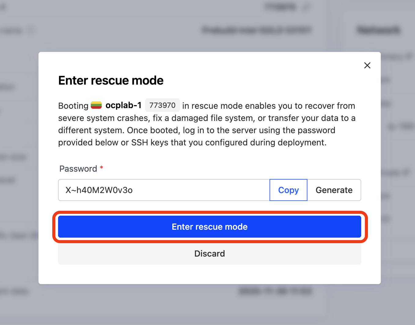
With our servers deployed, we can grab the MACs from each server using Rescue mode. From each server’s dashboard, click the Actions dropdown, then select Enter rescue mode.
Before configuring the network, we need to identify each server's physical network interfaces and their MAC addresses. These MAC addresses will be mapped to interface names (like eno1) in the static network configuration, ensuring the installer applies the correct network settings to the correct hardware.
This will open a modal. Simply click Enter rescue mode to boot the server into rescue mode. We don’t need a password for this process.
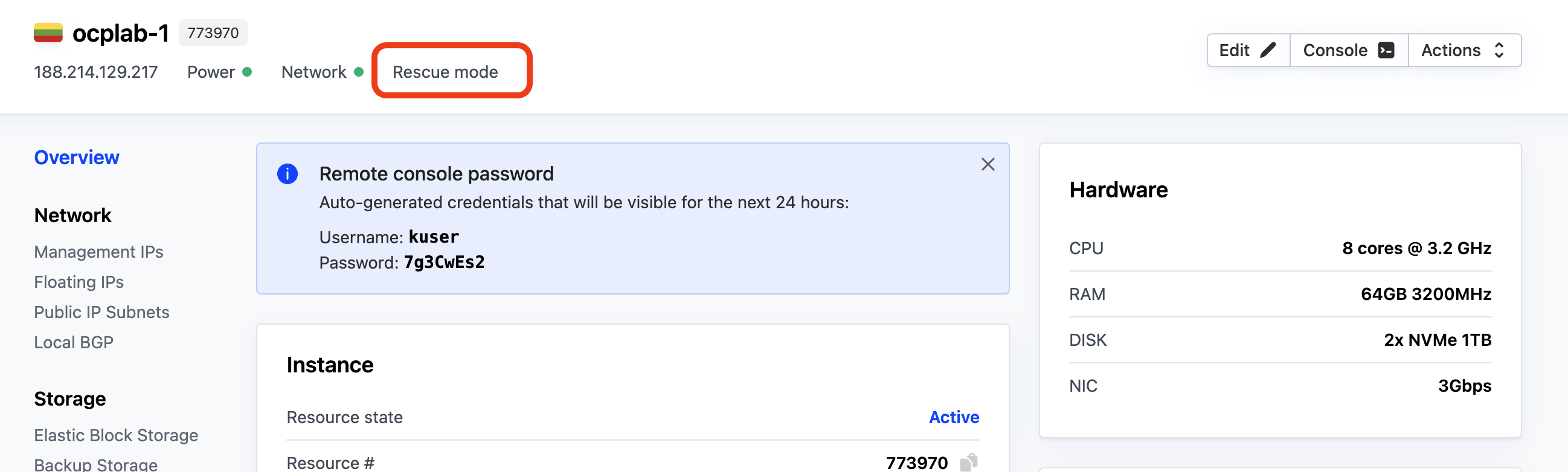
After a few minutes, the server should be in rescue mode. You can confirm this from the dashboard, look for the Rescue mode label near the top of the page.
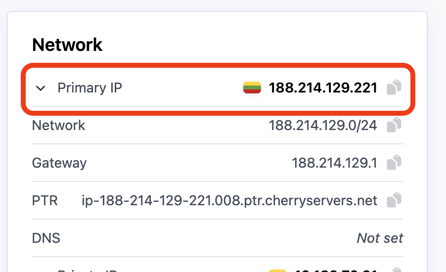
Once it is ready, open a terminal on your local computer and connect to each server with SSH:
ssh root@<server-public-ip>
Replace <server-public-ip> with each server’s Primary IP.
Next, run the following command to list the NICs and MACs:
ip -o link | awk -F': ' '{print $2}' | xargs -I{} bash -lc 'printf "%-10s " {}; cat /sys/class/net/{}/address'
This command lists all network interfaces and their MAC addresses. The ip -o link command lists interfaces in a single-line format, which we then parse to extract interface names and read their corresponding MAC addresses from the system.
The output should look like this:
Outputlo          00:00:00:00:00:00
eno1        3c:ec:ef:98:35:d4
eno2        3c:ec:ef:98:35:d5
Take note of the eno1 interface and MAC addresses. We will need those in the static network configuration phase.
Repeat the same process on the other two servers and save their details.
#Step 3: Create the cluster
Now that we have our servers and their MAC addresses, we can move on to creating the cluster.
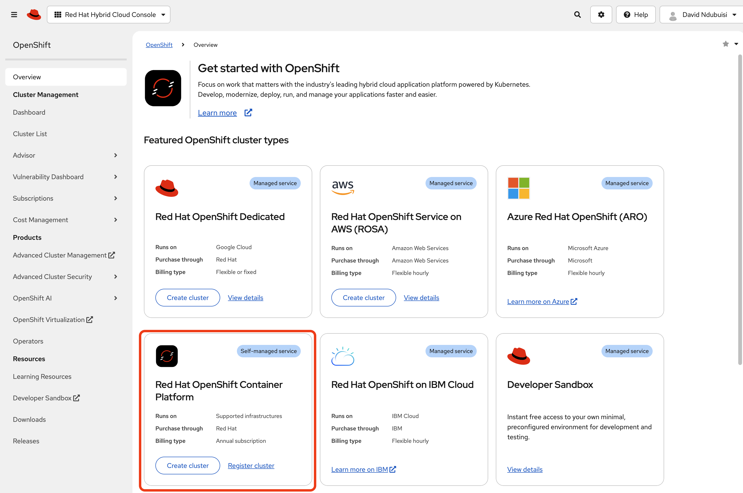
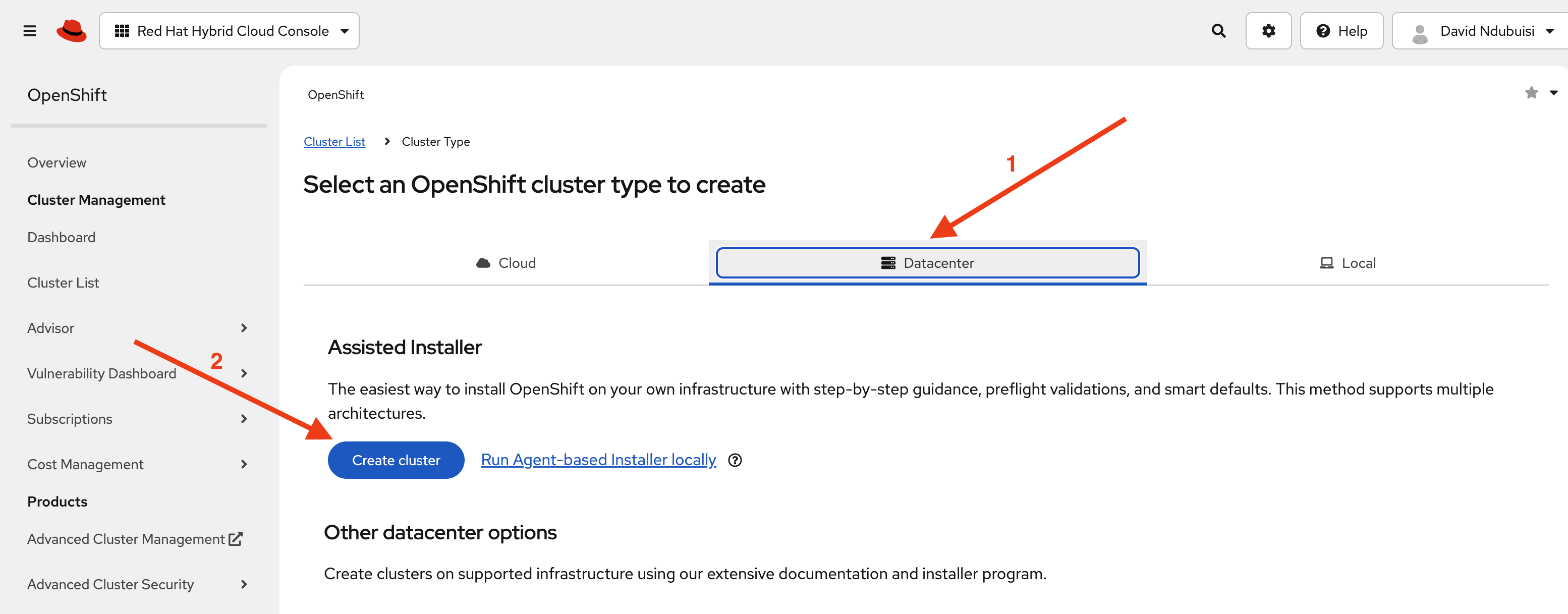
Head over to Red Hat’s Hybrid console. Under Red Hat OpenShift Container Platform, click Create cluster.
On the next page, choose Datacenter, then click Create cluster under Assisted Installer. This option gives us a guided installation that handles most of the setup automatically.
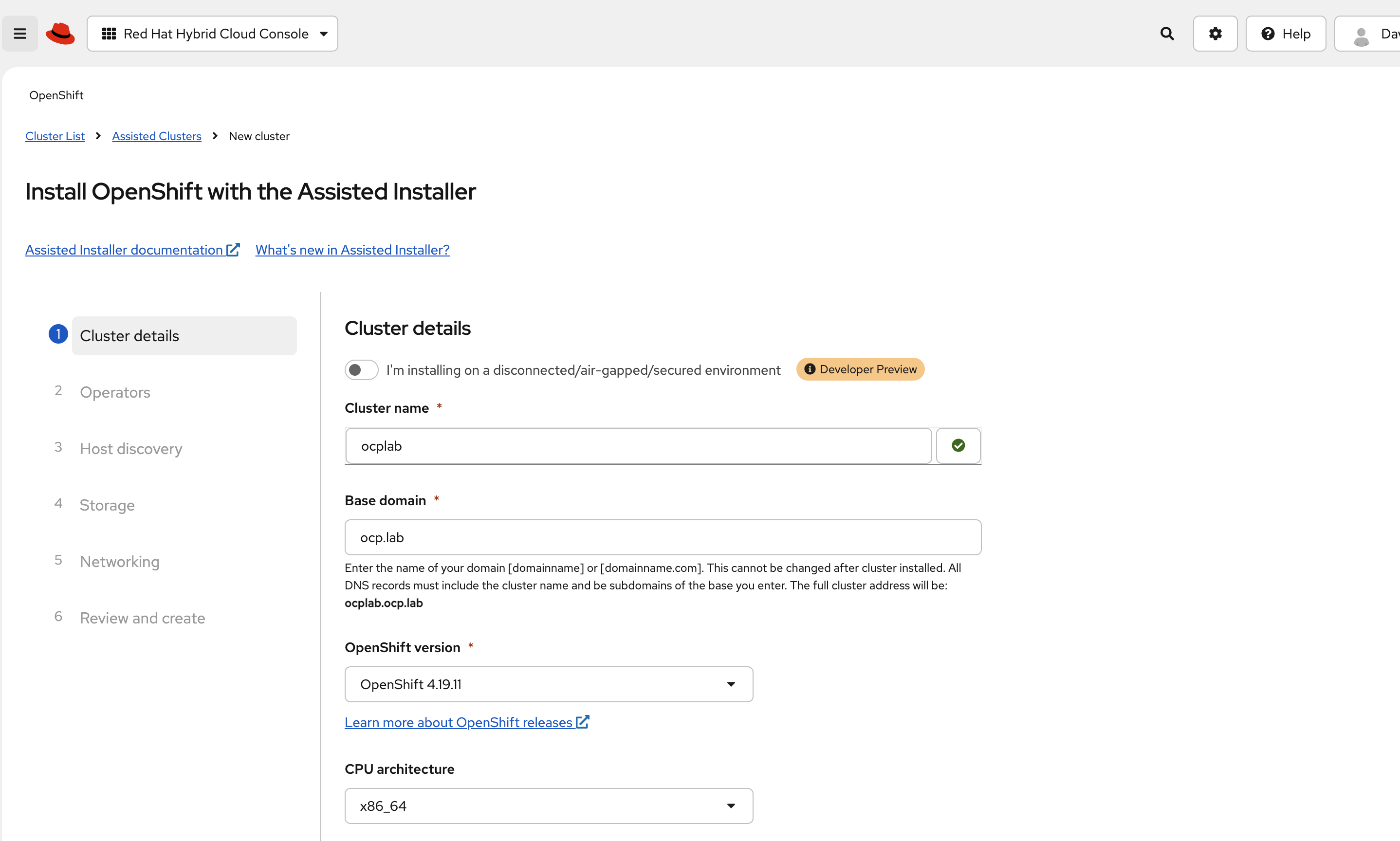
For this guide, we set the cluster name to ocplab and the base domain to ocp.lab. This means the API endpoint becomes api.ocplab.ocp.lab, and the console URL should be similar to console-openshift-console.apps.ocplab.ocp.lab. You can use your own names here, but keep them simple and consistent.
In most cases, the Pull secret field is already filled in. If it is empty, paste the pull secret you downloaded earlier. This key lets the installer pull container images during setup.
Leave the Integrate with external partner platforms field as it is. You can also skip custom manifests for now. It is easier to bring the cluster up cleanly and add extras later.
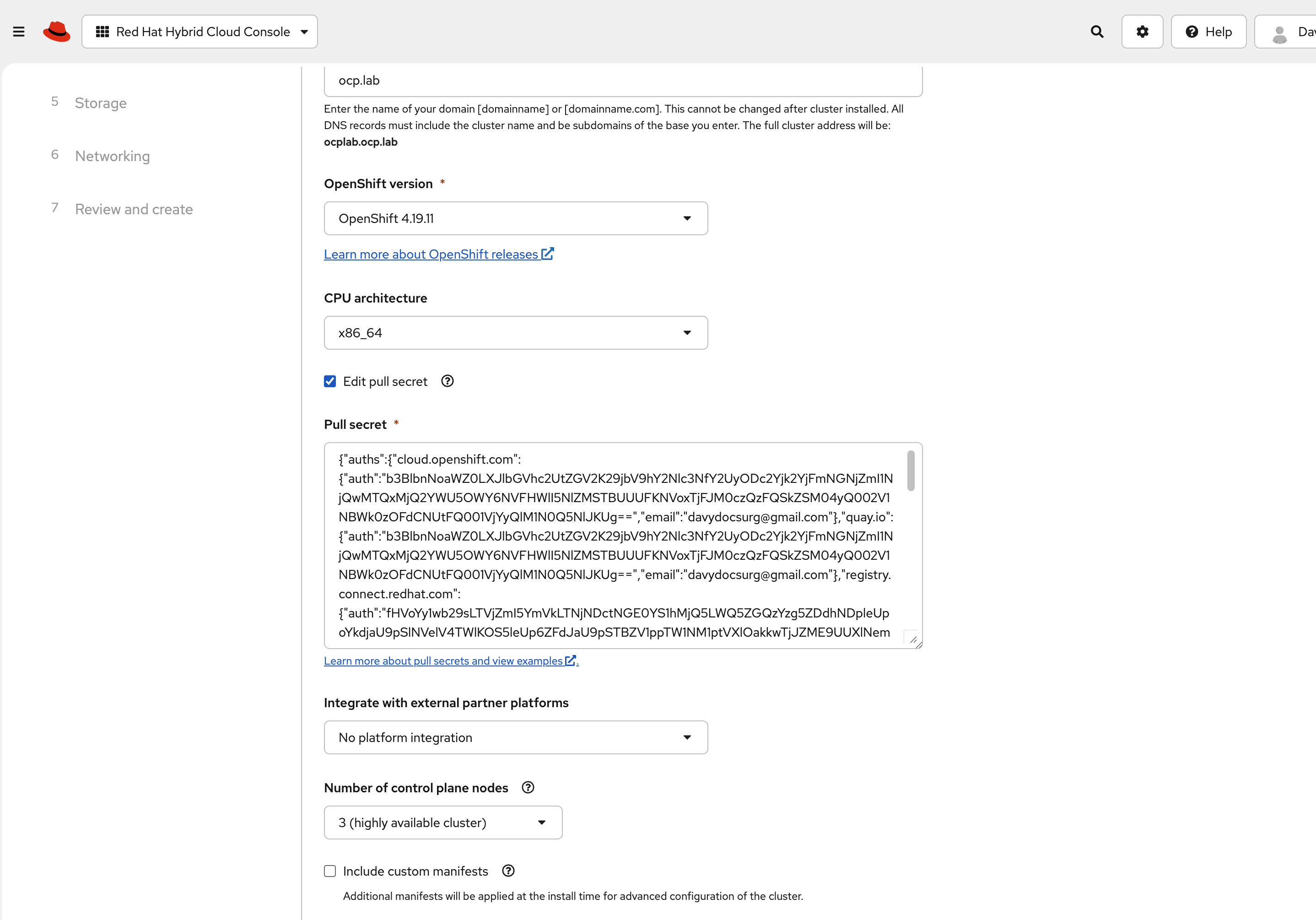
Next, set the cluster to run with three control plane nodes. That keeps the control plane highly available, even without separate workers.
For networking, select Static IP, bridges, and bonds. In our lab, we keep DHCP on the public interface for simplicity, but the private network uses static configuration for two reasons:
First, the cluster network runs on a tagged VLAN interface (eno1.2832). DHCP servers do not usually hand out addresses on VLAN subinterfaces, and if they do, the address may change after a reboot.
Second, OpenShift needs stable IP addresses for the control plane and for the virtual IPs that users connect to. Assign each control plane node a static IP on the private subnet and reserve two free IPs in the same range for the API and Ingress virtual IPs. These addresses must not be managed by DHCP or used by any other host.
Leave disk encryption disabled unless you have a specific reason to enable it.
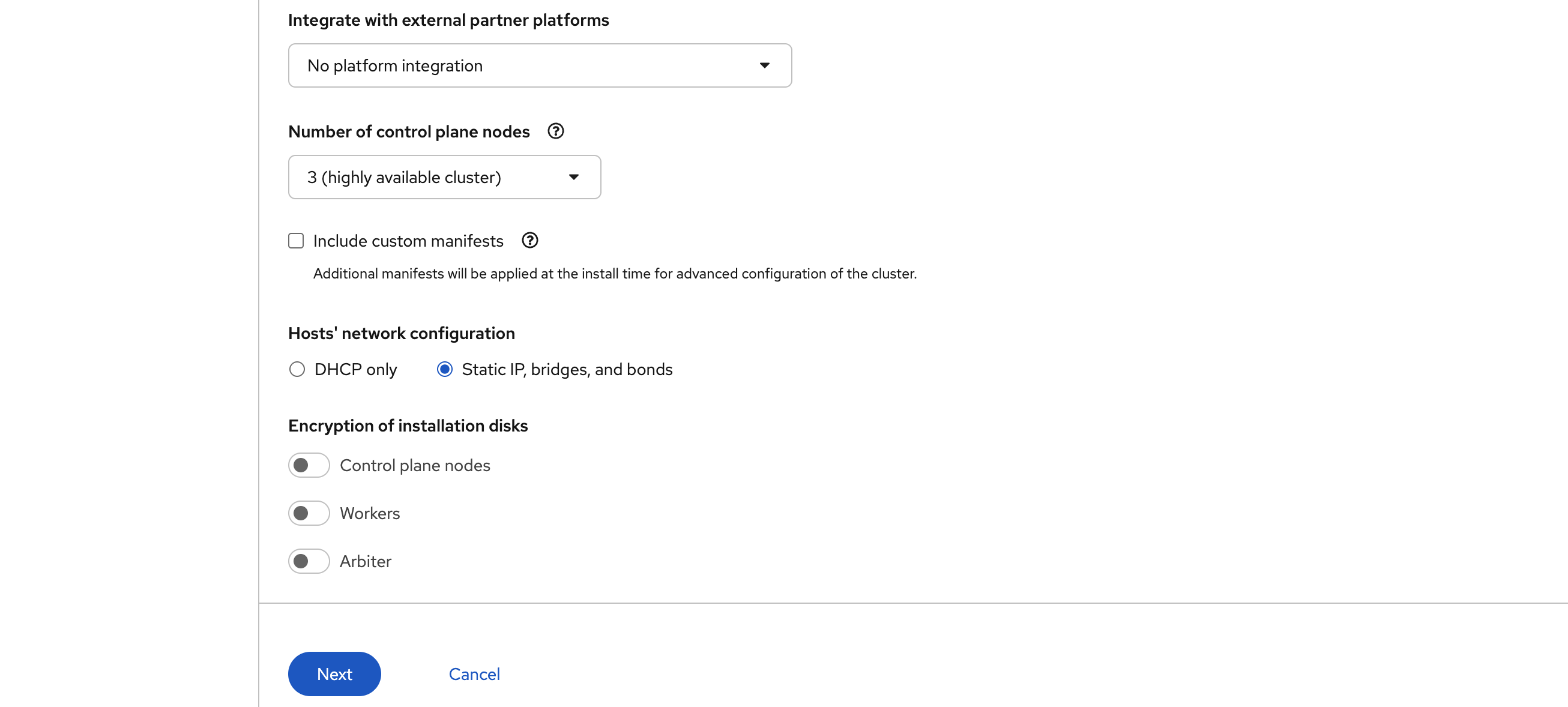
Finally, hit Next to continue.
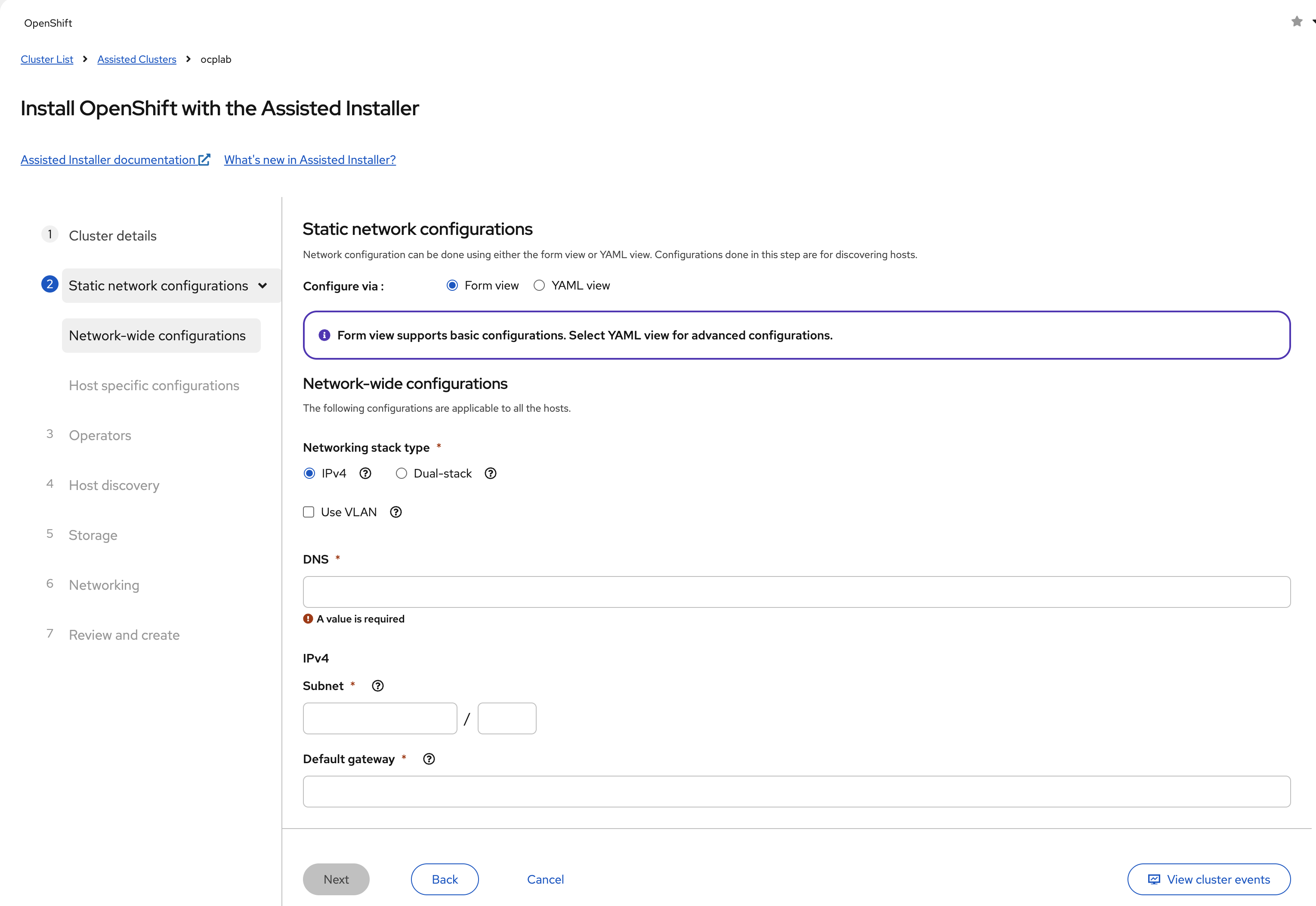
#Step 4: Static network configurations
This is the point where we define how each host connects to the public Internet and the private VLAN. The Assisted Installer starts by showing us a Form view, which is too limited for our setup.
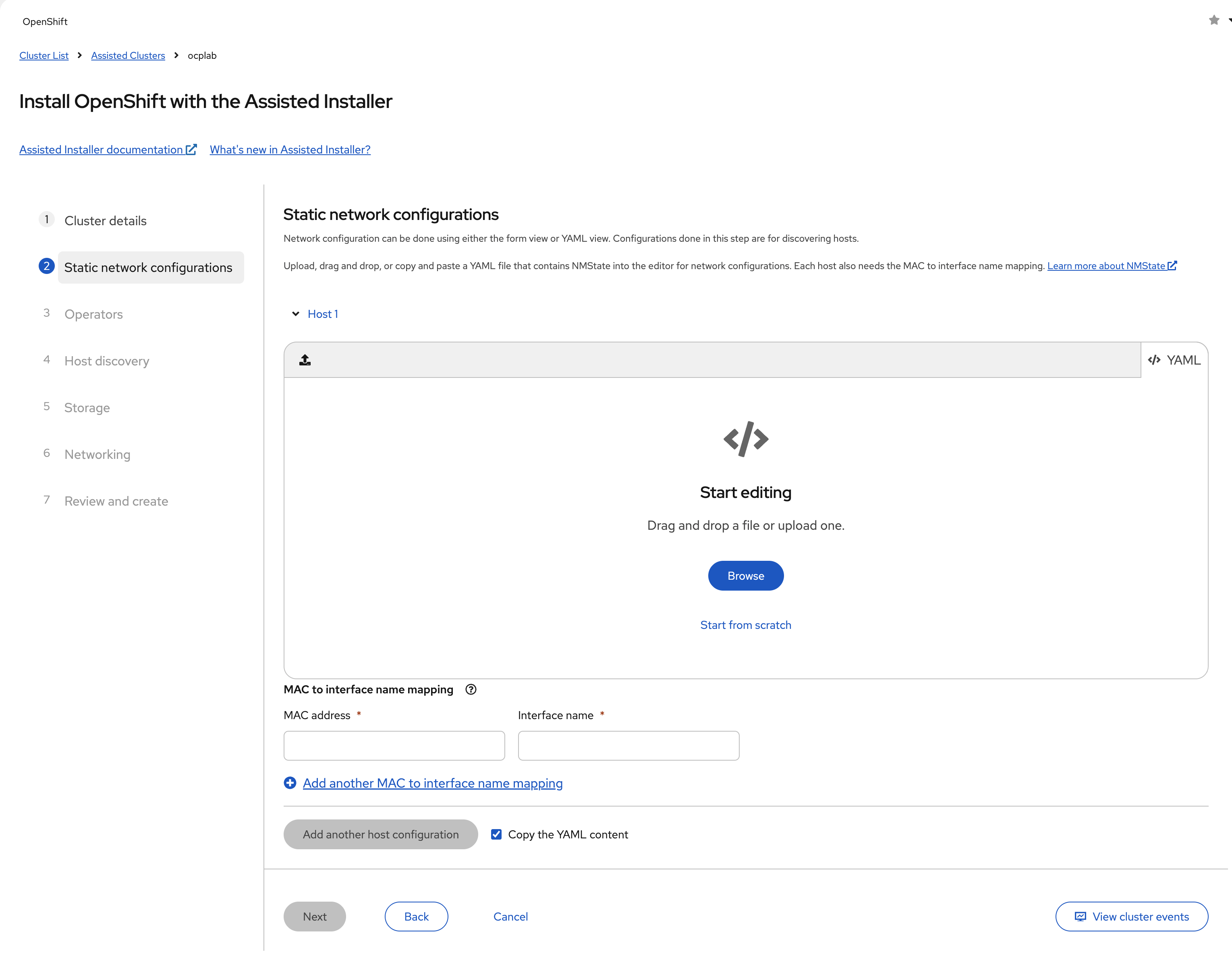
We need more control. Switch over to the YAML view so we can define bonds, VLANs, and static IPs properly.
Once you are in the YAML view, paste a configuration for each host. Each host uses the same structure.
We use eno1 as the primary interface with DHCP for public connectivity, allowing it to reach Red Hat services automatically. On top of eno1, we create a VLAN subinterface (eno1.2832) with a static IP for the private cluster network.
Here is the YAML template for the 3 hosts:
interfaces:
    - name: eno1
      type: ethernet
      state: up
      ipv4:
          enabled: true
          dhcp: true
      ipv6:
          enabled: false

    - name: eno1.<vlan-id>
      type: vlan
      state: up
      vlan:
          base-iface: eno1
          id: <vlan-id>
      ipv4:
          enabled: true
          dhcp: false
          address:
              - ip: <private-vlan-ip>
                prefix-length: <subnet-prefix>
      ipv6:
          enabled: false
This configuration serves two purposes: the public interface (eno1) with DHCP provides Internet connectivity for downloading container images and reaching Red Hat services.
The VLAN subinterface (eno1.2832) with static IPs creates a stable private network where OpenShift cluster communication happens. Static IPs are required here because the cluster's API and Ingress virtual IPs must remain constant, and DHCP servers typically don't assign addresses to VLAN subinterfaces.
The only parts you change are the placeholders.
<vlan-id> is the VLAN number for your private network.
<private-vlan-ip> is the static address for that server. Each host needs a unique IP from the same range.
<subnet-prefix> is the prefix length for that subnet. For example, if your VLAN network is 10.182.70.0/24, then the prefix length is 24. If your provider gives you something different, use the correct number for your range.
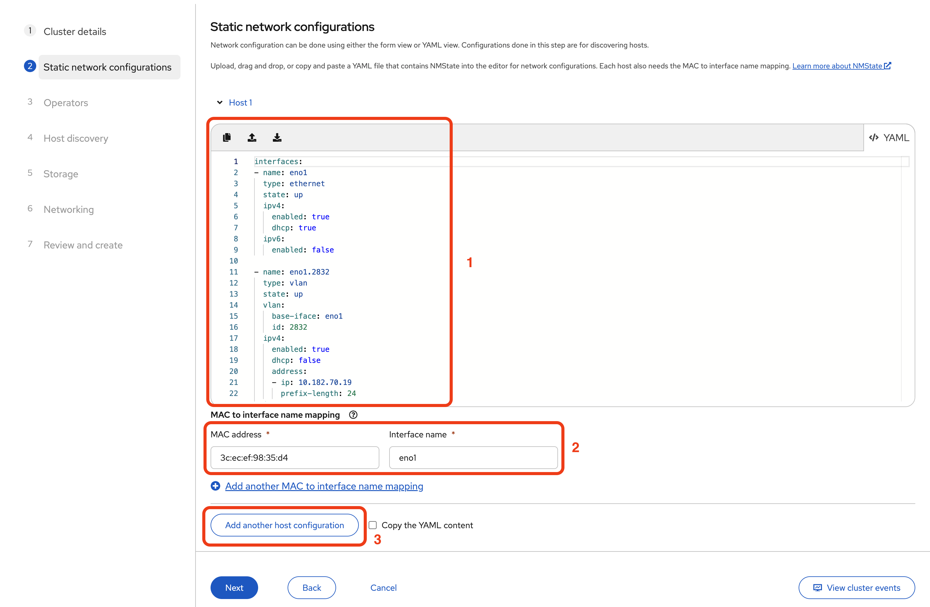
For example, here is the actual YAML configuration we used for Host 1:
interfaces:
    - name: eno1
      type: ethernet
      state: up
      ipv4:
          enabled: true
          dhcp: true
      ipv6:
          enabled: false

    - name: eno1.2832
      type: vlan
      state: up
      vlan:
          base-iface: eno1
          id: 2832
      ipv4:
          enabled: true
          dhcp: false
          address:
              - ip: 10.182.70.19
                prefix-length: 24
      ipv6:
          enabled: false
Remember, we already collected the NIC MAC addresses back in Step 2. That is where we identified which physical port is eno1. We use that same name here in the configuration. While your servers have two NICs (eno1 and eno2), this configuration uses only eno1 for simplicity.
In our setup:
- VLAN ID: 2832 (assigned by Cherry Servers for our private network)
- Host 1 IP: 10.182.70.19
- Host 2 IP: 10.182.70.21
- Host 3 IP: 10.182.70.29
Your values will differ. Replace them with the ones that match your VLAN.
For Host 1:
- Paste your YAML configuration into the editor.
- In the MAC to interface name mapping section below, enter the MAC address you collected for eno1.
- Set the interface name to eno1.
- Click Add another host configuration.
Repeat these steps for Host 2 and Host 3, using each server's unique static IP and MAC address.
When finished, all three hosts should appear in the configuration list with their MAC mappings.
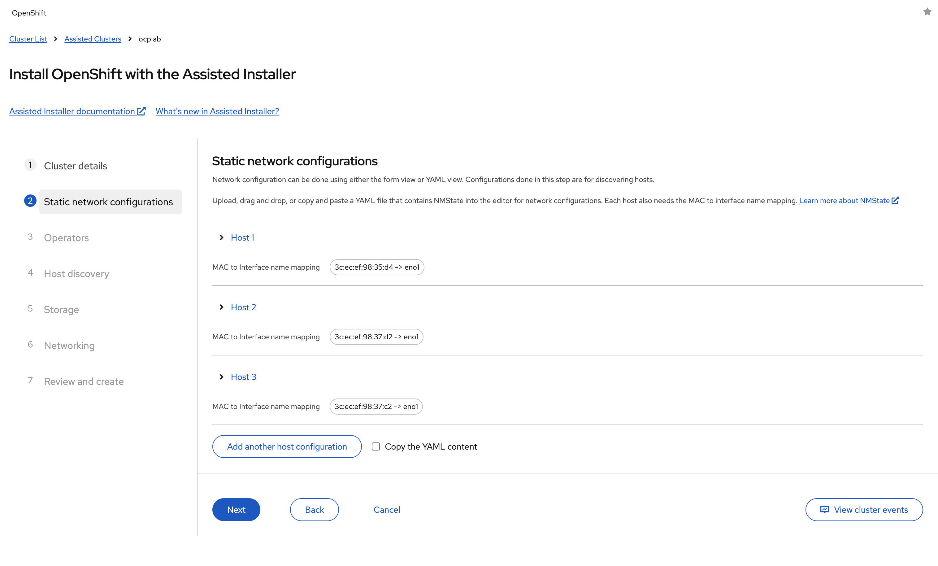
Once all hosts are configured, click Next to continue.
#Step 5: Choose Operators
The Assisted Installer gives us the option to add Operators during the initial setup. These include features like Virtualization, which allows us to run virtual machines directly on OpenShift, or OpenShift AI, which is used for GPU-based workloads.
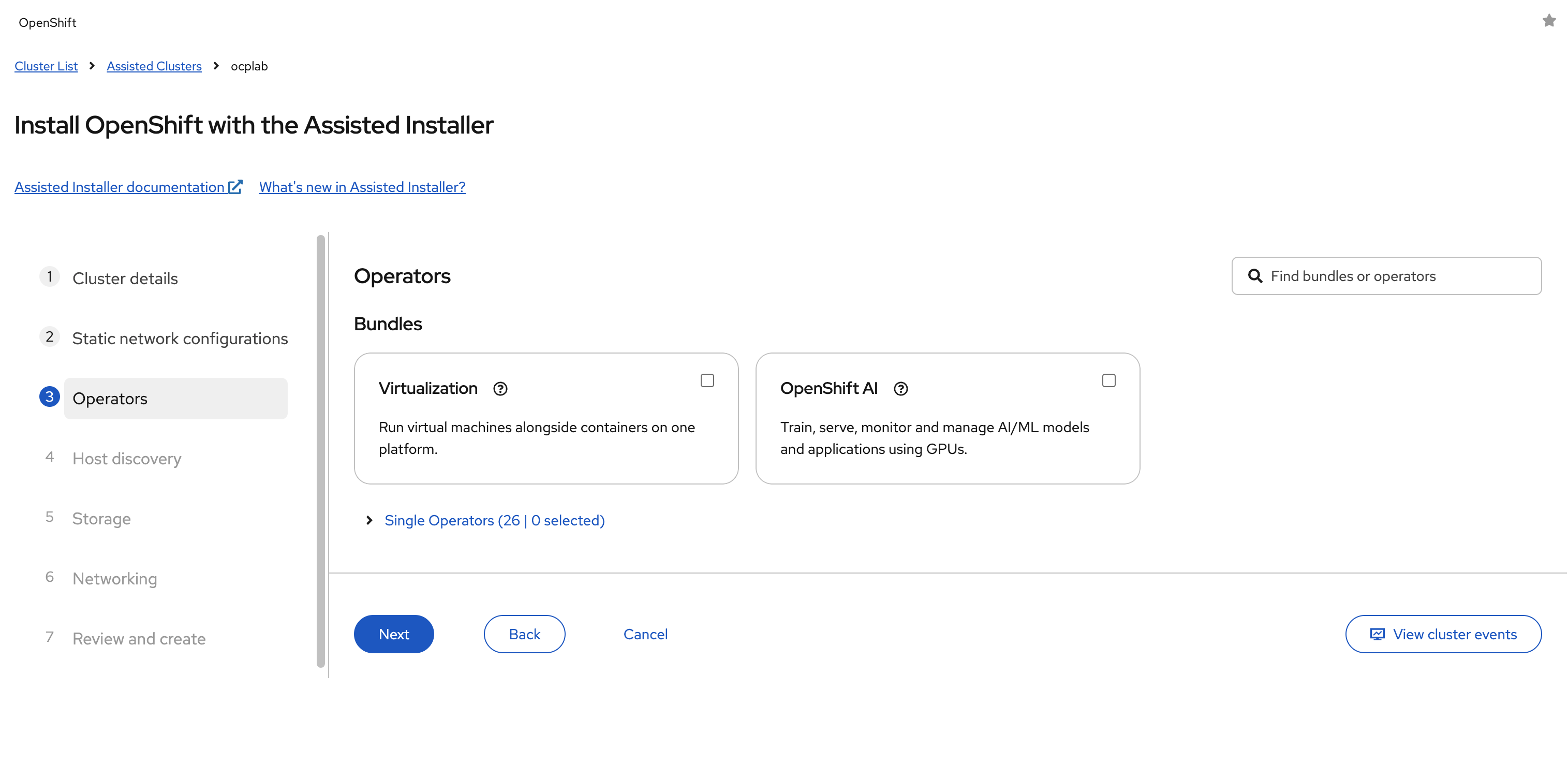
For this guide, we leave every box unchecked. Adding Operators later is straightforward, and it is usually safer to keep the first installation clean.
Extra components at this stage can introduce errors or make troubleshooting more complicated.
Click Next to continue.
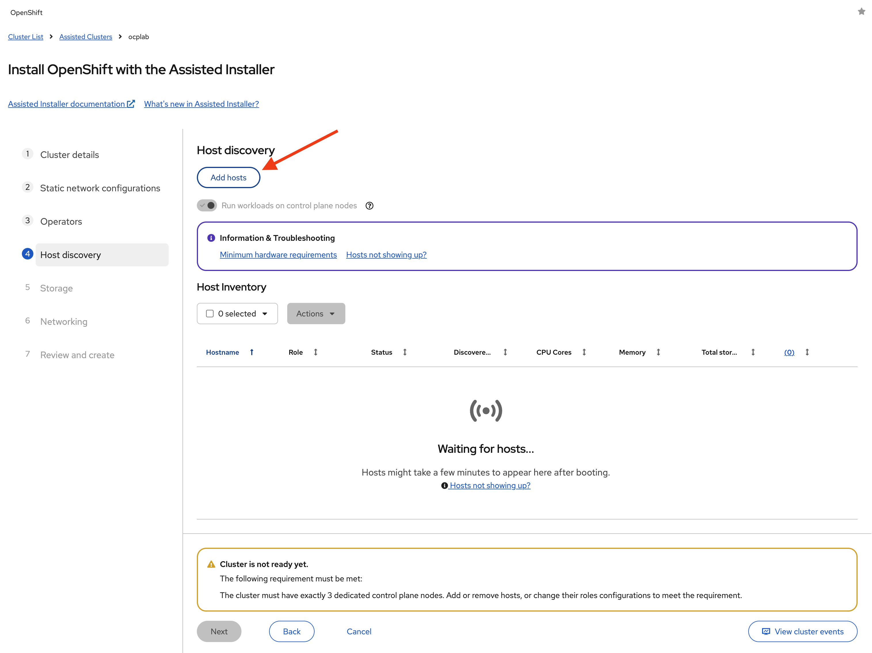
#Step 6: Host discovery
Here, we bring our servers into the Assisted Installer. We do that with a Discovery ISO. The ISO contains the static network configuration we set earlier. Once a server boots from it, the Assisted Installer will recognize it and add it to the host inventory.
#Generate the Discovery ISO
Under Host discovery, click Add hosts.
Next, paste your SSH public key into the field. This will be tied to the core user on each node, so later on, we can log in if we need to troubleshoot or set up tunnels. Leave every other field as default.
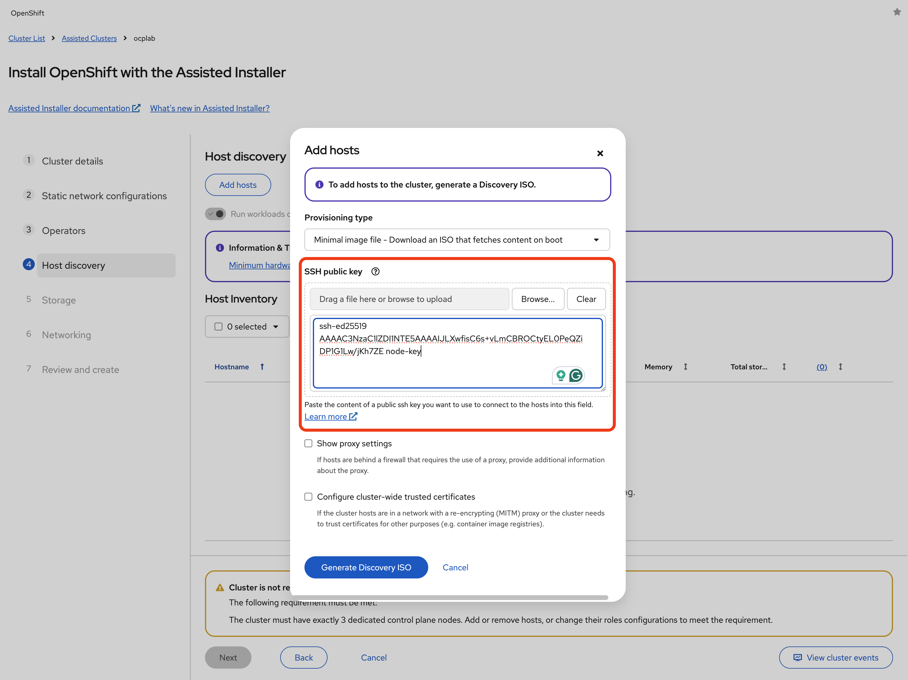
Click Generate Discovery ISO to generate the ISO file. Then, download the ISO file by clicking on Download Discovery ISO.
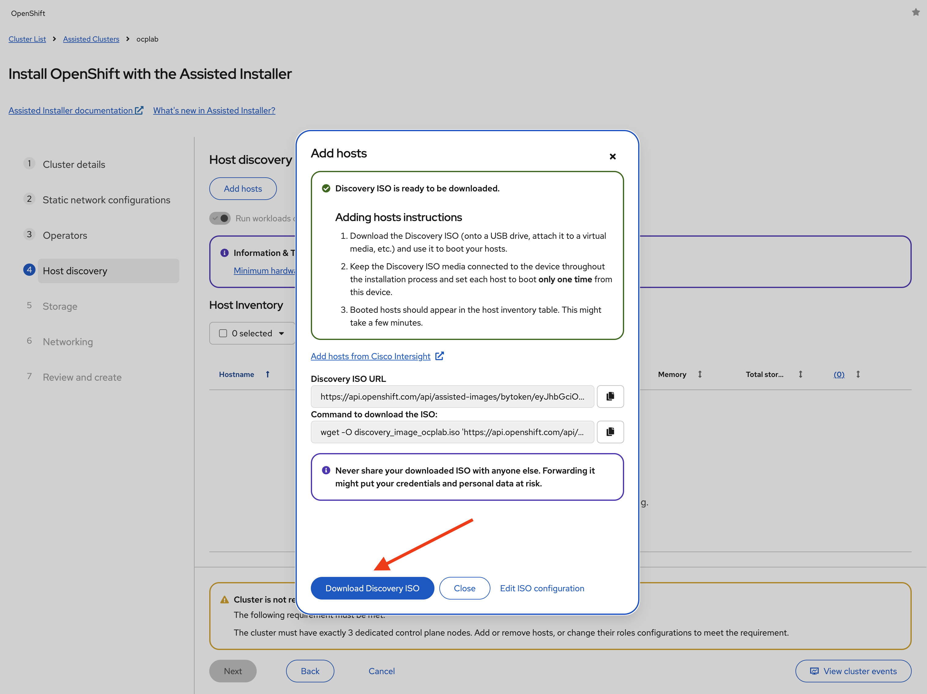
#Mount the ISO on the servers
Now we can mount the ISO to each bare metal node. Cherry provides us with Supermicro BMC (IPMI) access for this.
First, we log in to the BMC web console of each server. Back in Cherry Servers’ dashboard, click on the first server (ocplab-1):
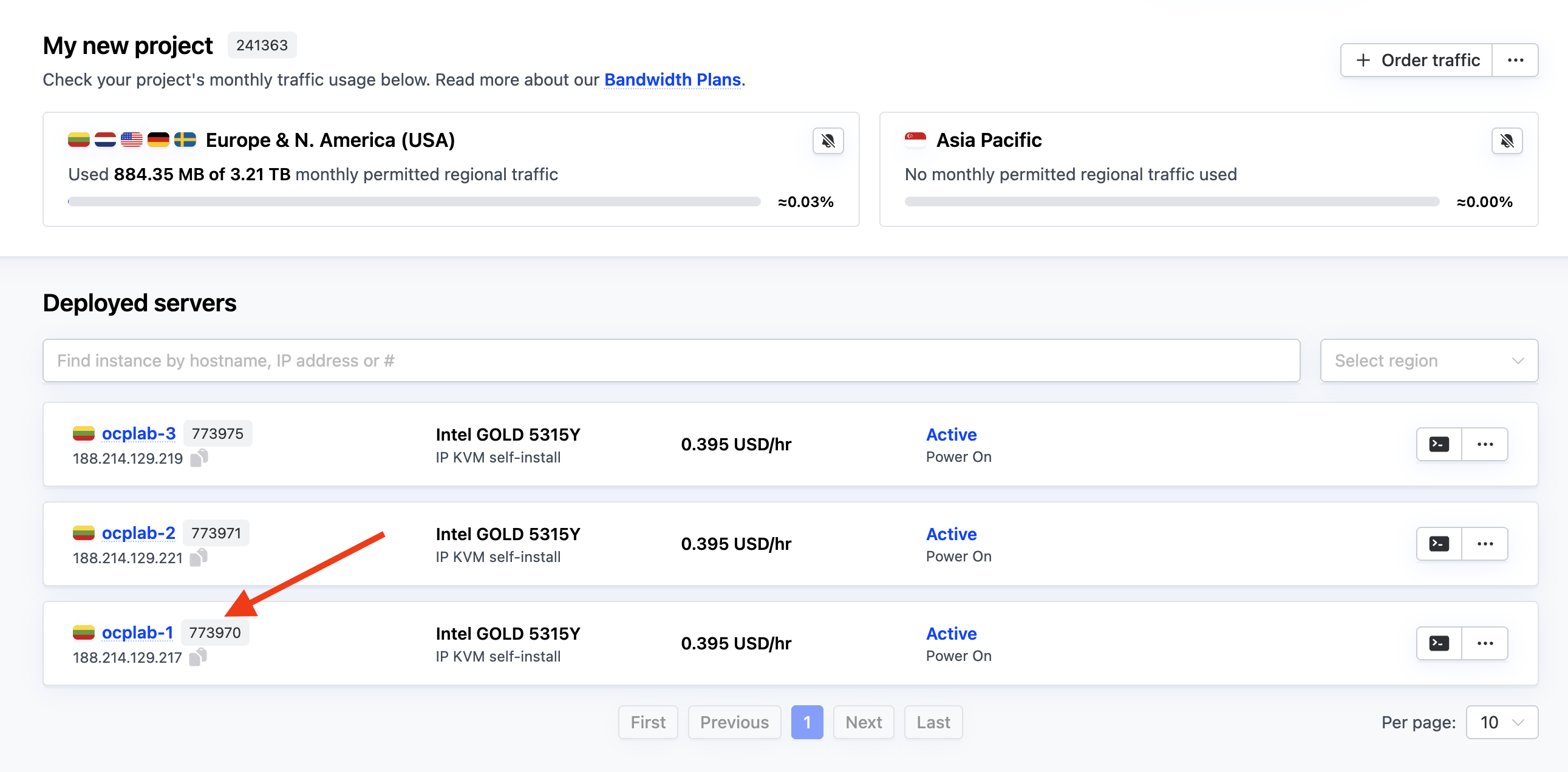
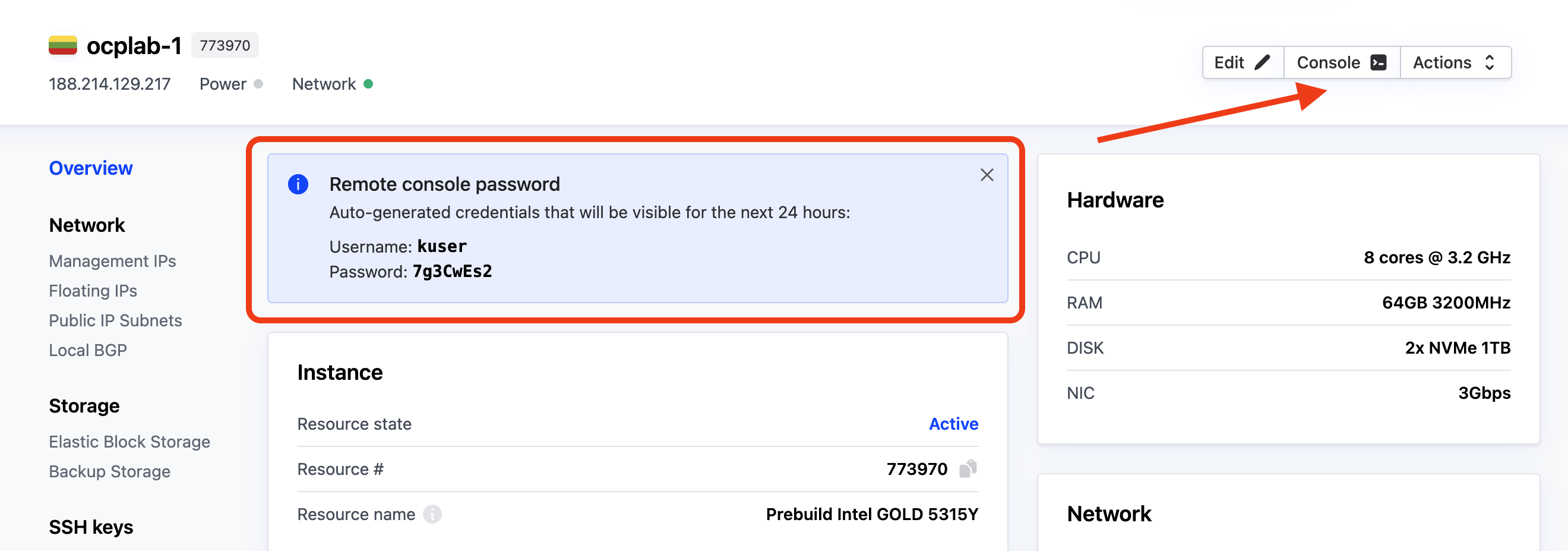
This leads to the details page. Next, copy your server’s username and password and click on Console.
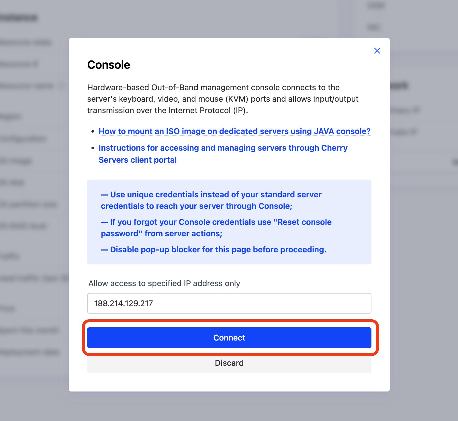
This opens a modal. Click on Connect to proceed.
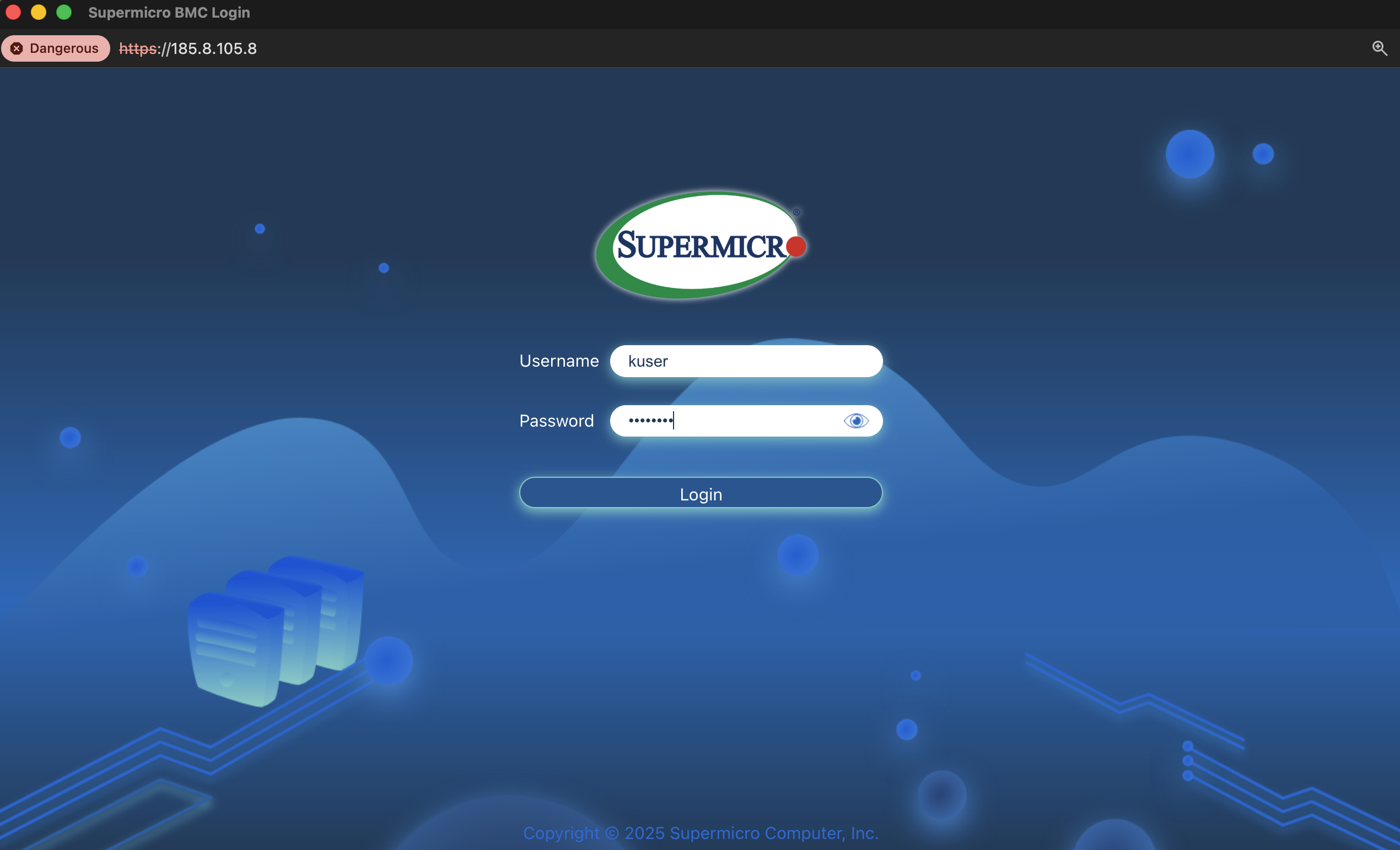
We should see the Supermicro BMC login page. Enter the username and password you copied earlier and click Login.
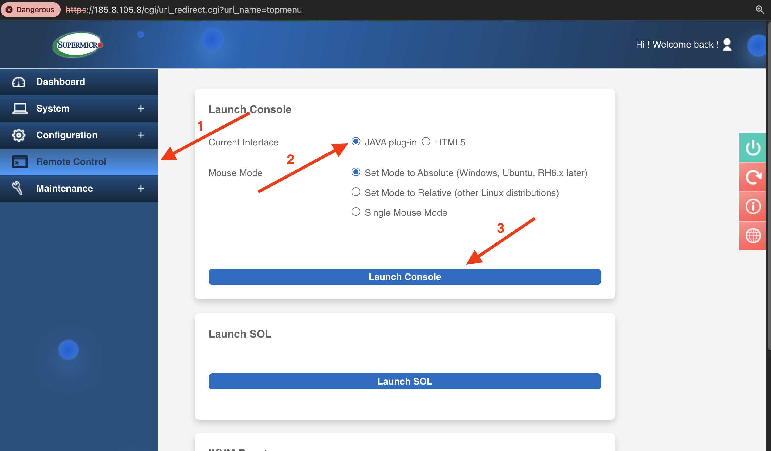
After logging in to the BMC, navigate to Remote Control in the left sidebar, select the JAVA plug-in option, and click Launch Console to download the JNLP file.
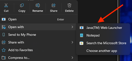
Open this file with Java(™) Web Launcher (you may need to right-click and select “Open with” if it does not launch automatically).
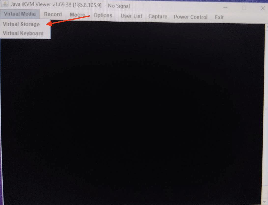
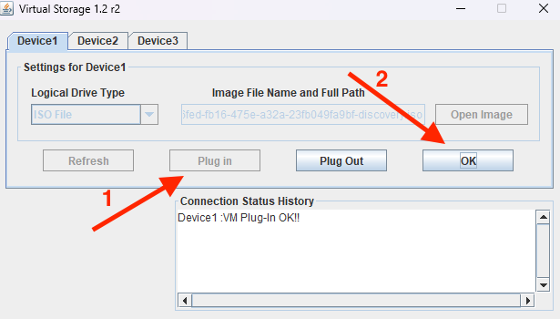
Once it is open, click Virtual Media on the top menu**,** then select Virtual Storage.
This will open up a pop-up window, showing tabs for Device1, Device2, and Device3.
Under Device 1, set Logical Drive Type to ISO File. Then, click Open Image to browse and select the ISO file you downloaded earlier.
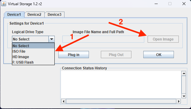
Next, click the Plug in button to attach the ISO file. Finally, click OK to confirm. You should see a confirmation message: Device 1: VM Plug-in OK!!
With the ISO file mounted, we can now reboot the server. Click Power Control and select Set Power Reset.
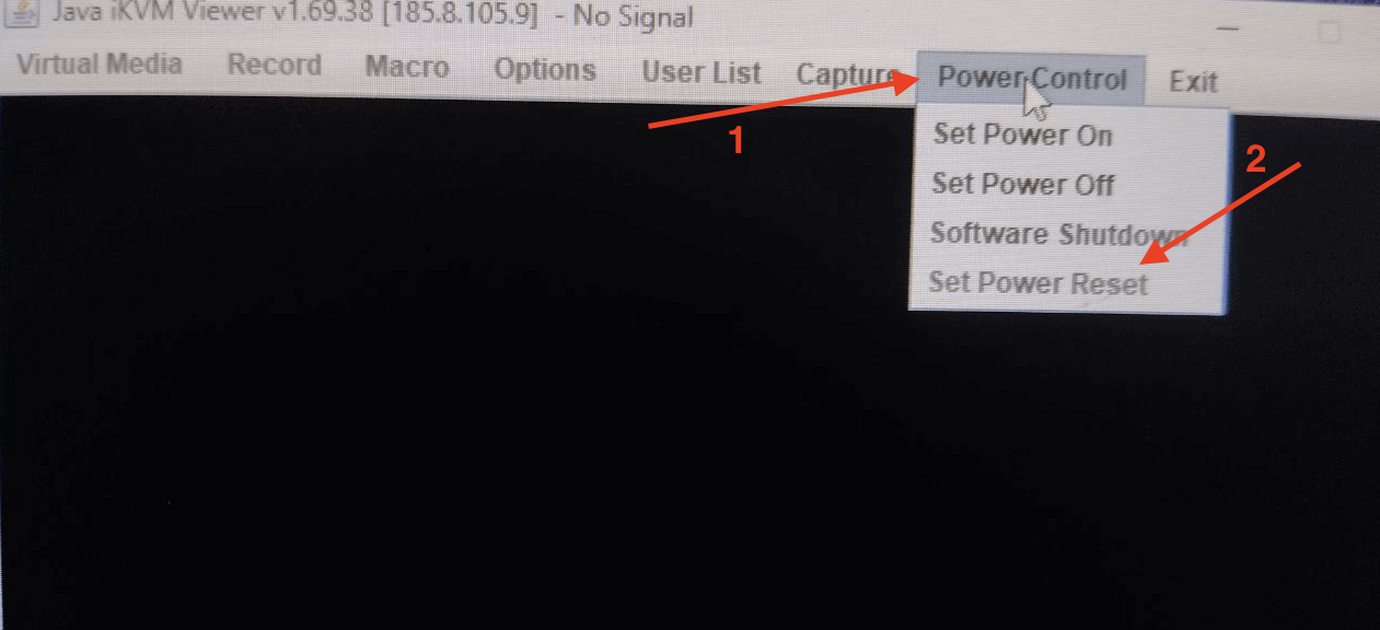
If your server is not powered on yet, simply select Set Power On.
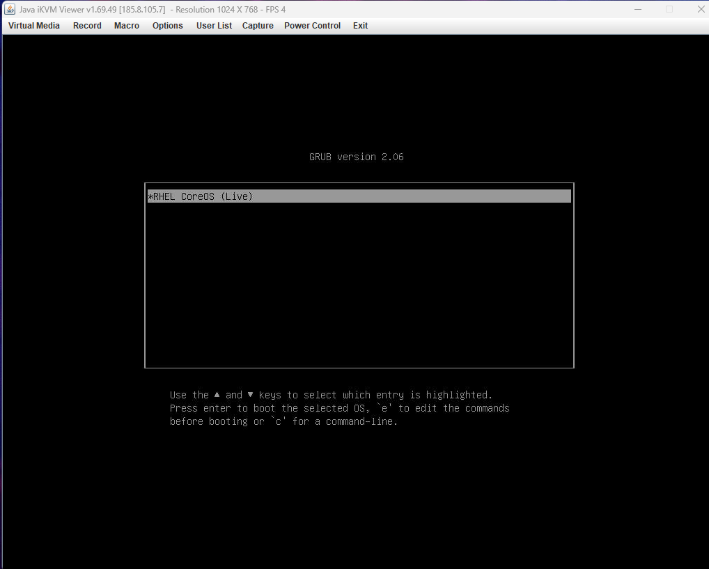
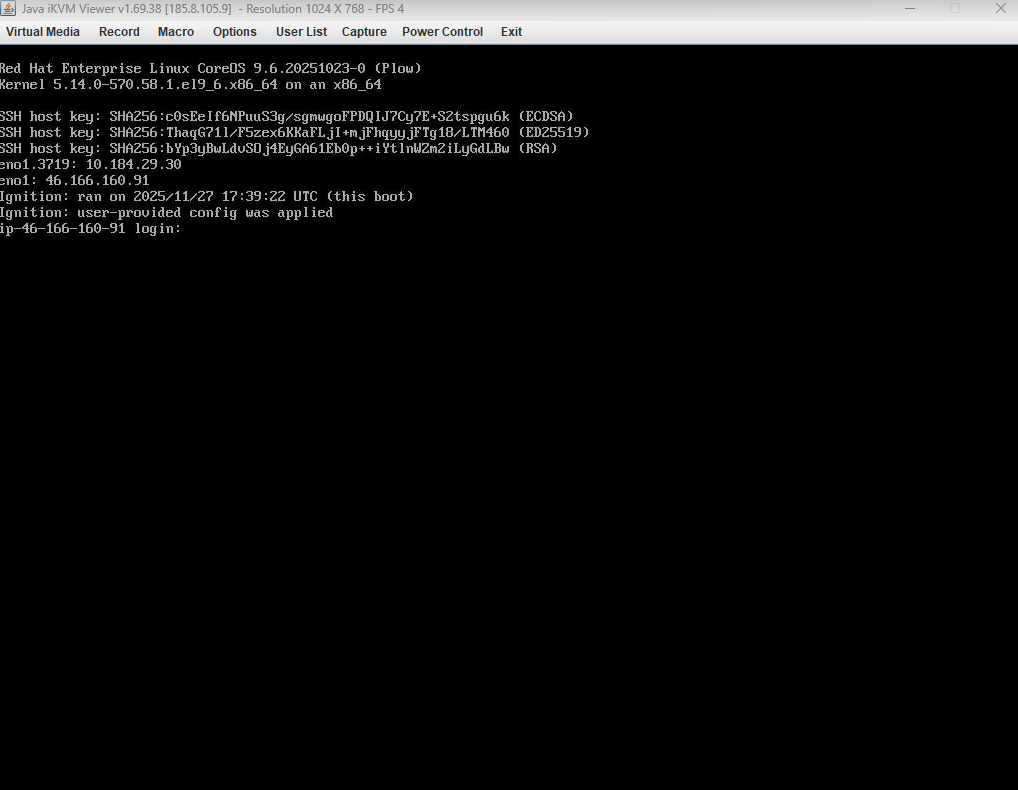
While the server reboots, the console will show the RHEL CoreOS (Live) GRUB menu; press ENTER to continue.
You will see the Ignition process run automatically. It applies the static network settings, contacts the Assisted Installer, and registers the host.
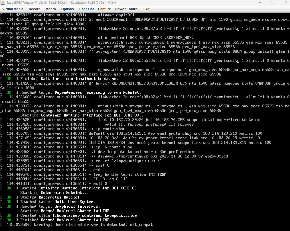
Eventually, you will see a confirmation message that the user-provided configuration has been applied.
Now, repeat this entire process for the other two servers. Each one must boot from the Discovery ISO and complete Ignition.
#Verify in the Assisted Installer
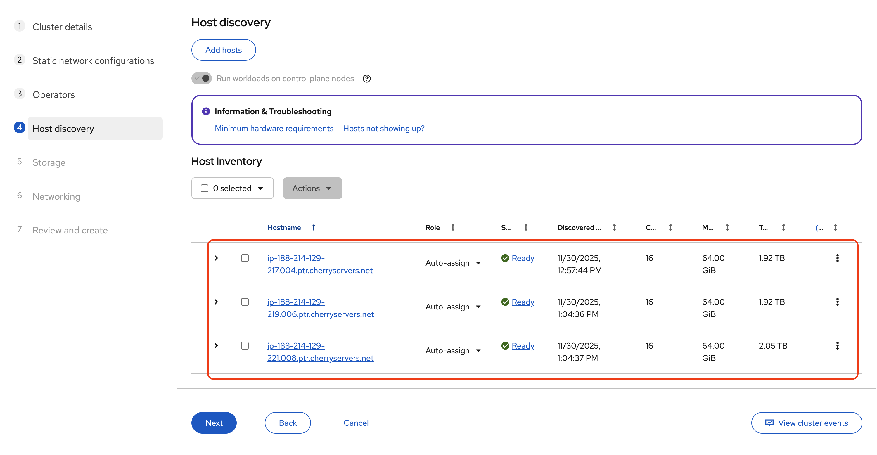
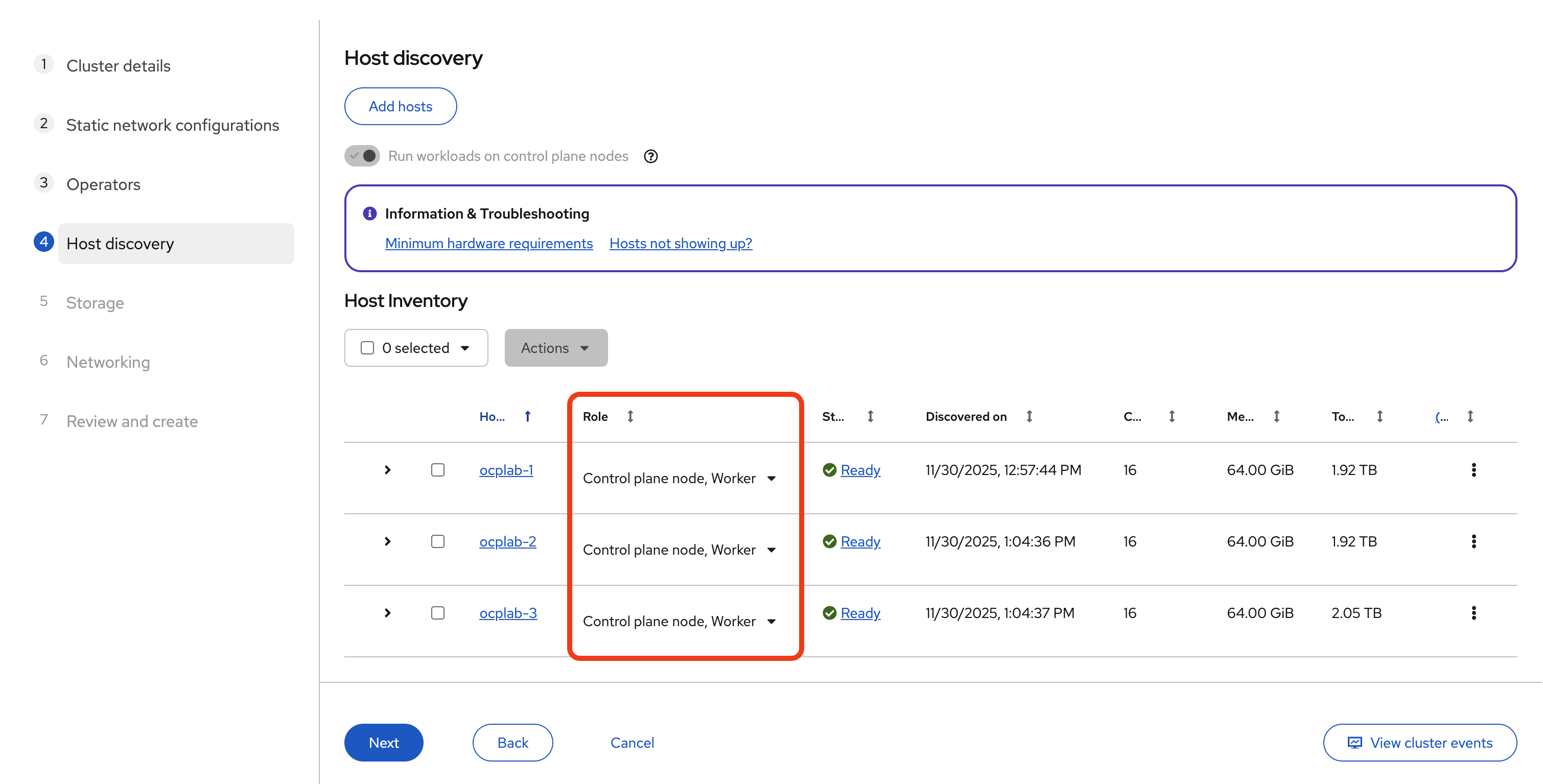
With all three servers successfully booted from the Discovery ISO, they will automatically register with the Assisted Installer. Return to the Assisted Installer's Host Inventory page to verify they have appeared.
At first, each one may appear as Discovering or Pending. After some time, they should switch to Ready. Wait until all three servers reach that state before going further.
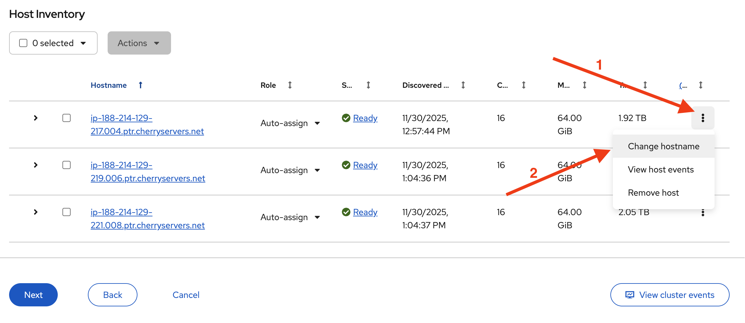
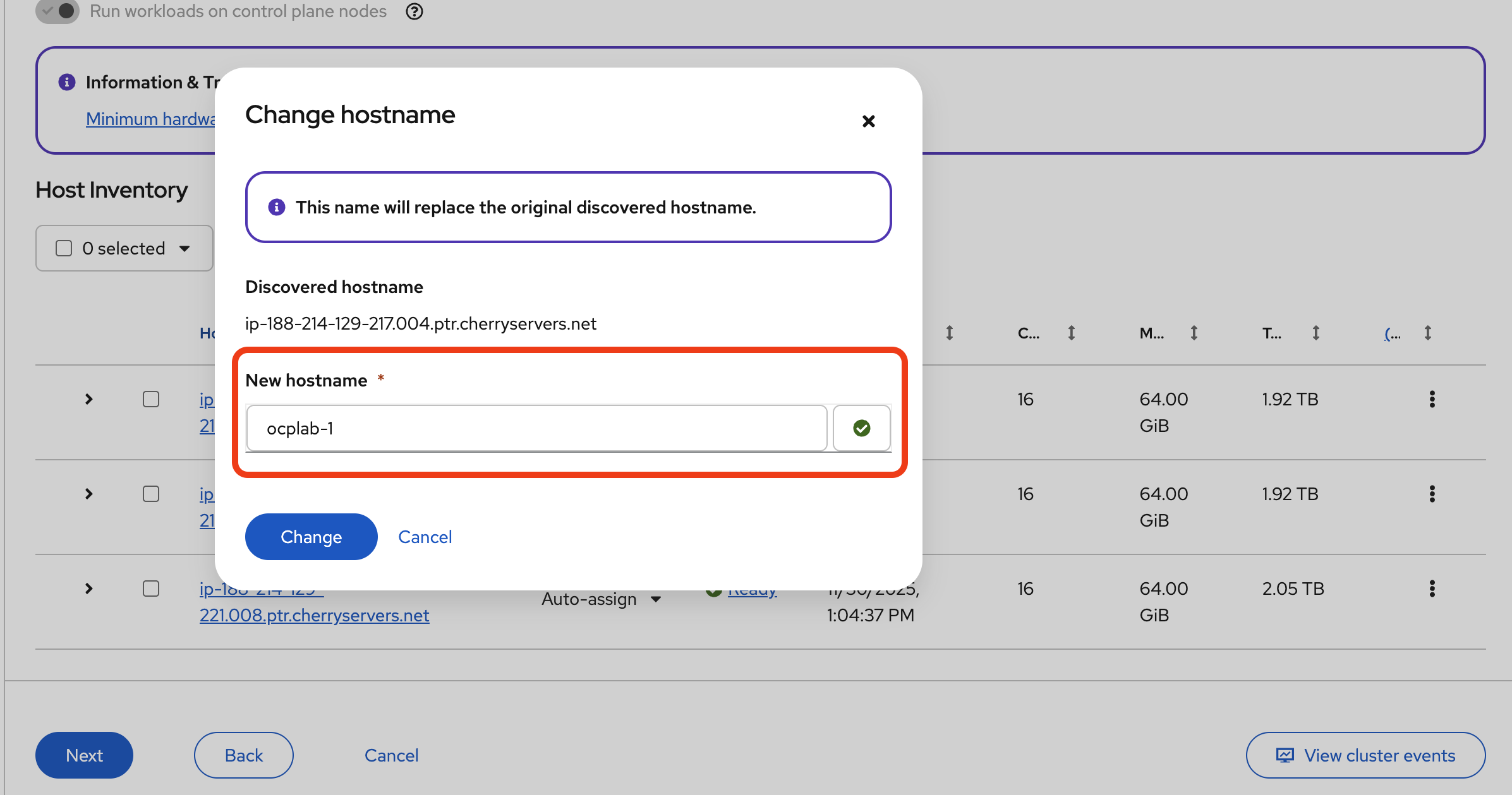
Once they are ready, it is good practice to rename them to something more readable. For each host, click the actions menu (the three-dot icon at the end of the row) and choose Change hostname.
Then, click Change to save.
For this guide, we used the same name as our servers. You can use something better or simpler.
Next, assign their roles. For this setup, each host will serve as both a Control plane node and a Worker. Change each host’s role to Control plane node, Worker. That way, we still get a highly available control plane without needing extra hardware for separate workers.
Now we can proceed to the next step by clicking Next.
#Step 7: Storage
Moving on to the storage step. This is where we pick the installation disk for each host. The Assisted Installer will list all the available drives it detects.
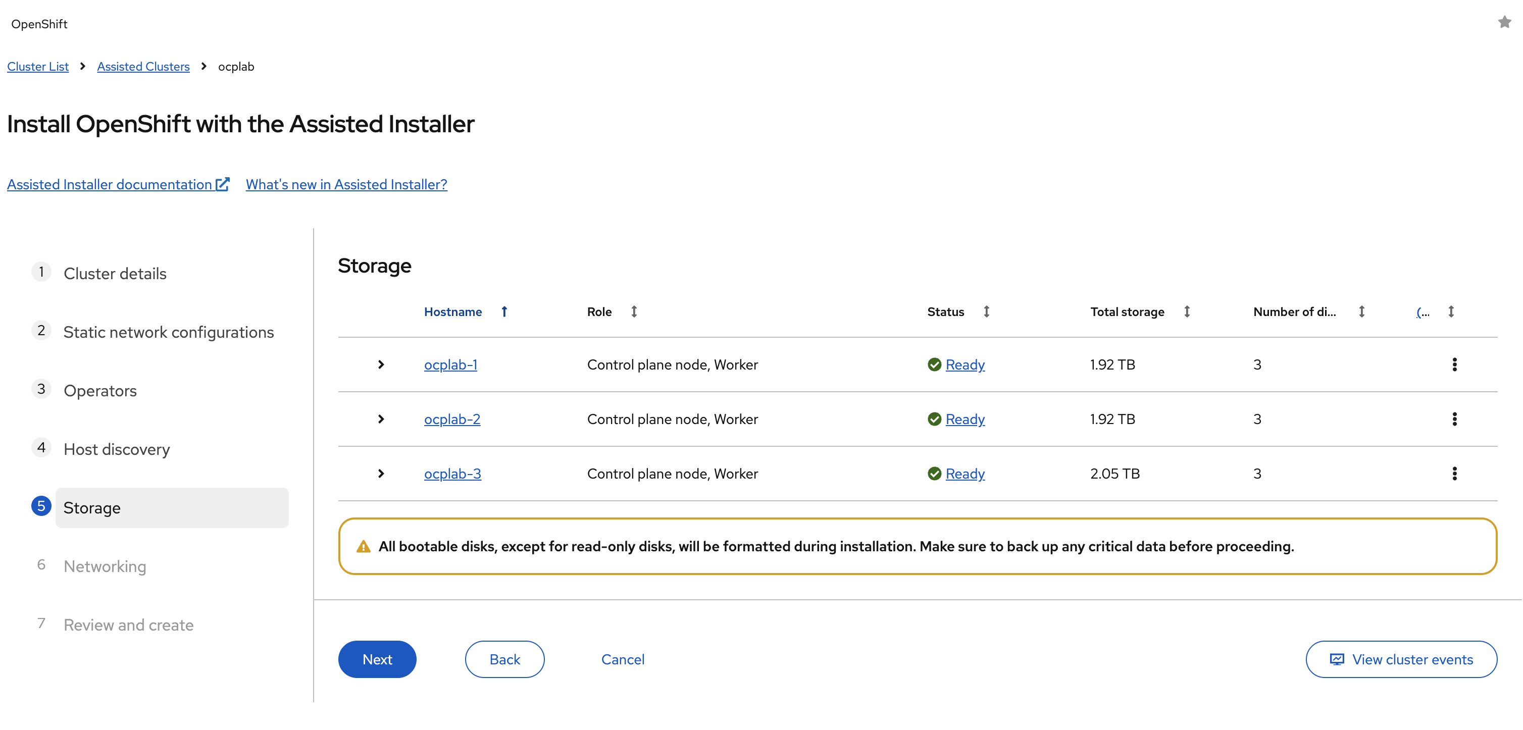
Some servers will show more than one disk. For example, you may see the main SSDs and also smaller virtual devices like the mounted ISO (sr0). The installer will often automatically pick the right disk for you. Still, it is worth double-checking. The installation disk should be the main SSD that OpenShift will use for RHCOS and all cluster data.
If your server has multiple SSDs, make sure the correct one is selected. Once each host has the right disk marked as the installation disk, click Next to continue.
Please note that the installer will completely wipe the disk you select. Do not pick a drive that has data you want to keep.
#Step 8: Networking
This step wires the cluster together. Leave Network Management on Cluster-Managed Networking. OpenShift will handle the internal overlay and the service networks. No need to change that here. We also stay on IPv4 only.
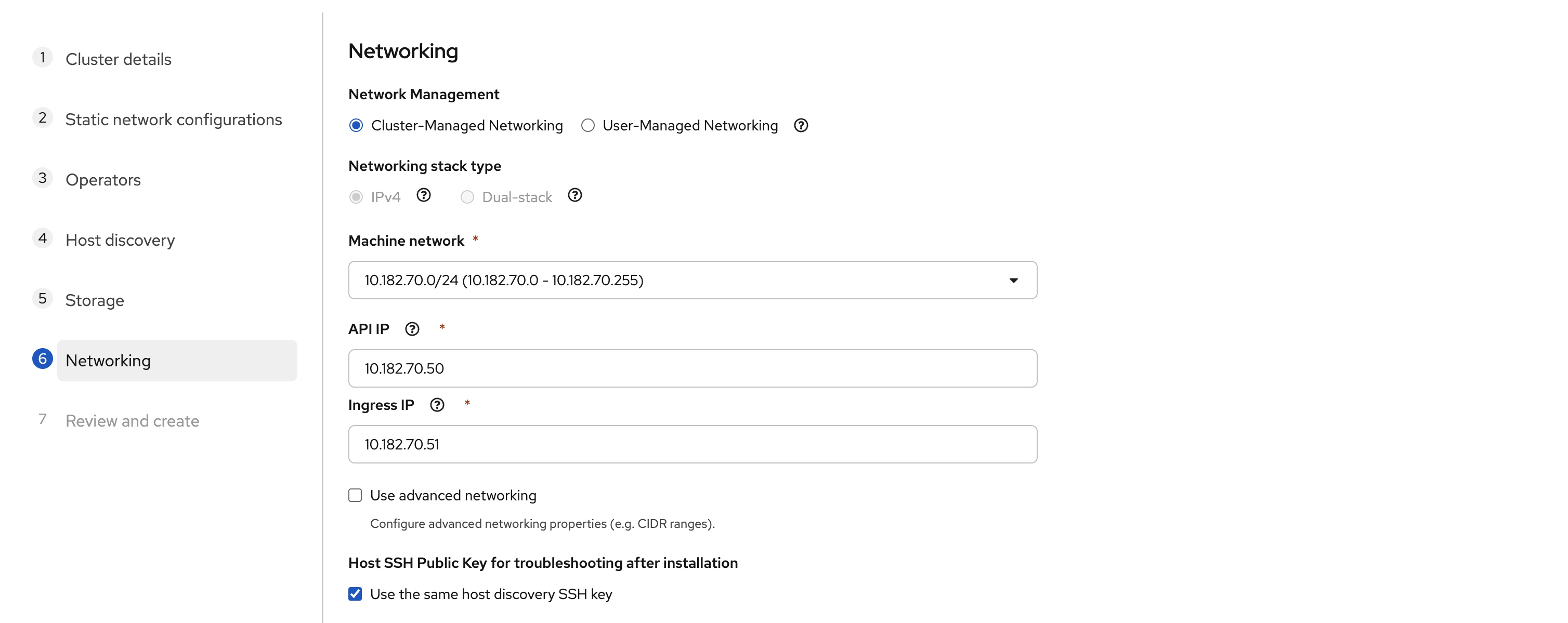
The Machine network is usually auto-detected. In our case, it showed 10.182.70.0/24. This matches the VLAN we used in the static YAML configuration earlier.
For you, the value may be different. However, it must match the subnet where your bonded VLAN IPs sit. If it does not line up with what you configured in the previous step, stop and correct it before going further.
For the API IP, pick a free and unused address inside the same subnet. For example, we used 10.182.70.50. Do not pick the gateway (.1 in most networks), and do not reuse one of your node IPs. This API IP becomes the endpoint for the Kubernetes API and also for the oc client.
For the Ingress IP, choose another free address from the same subnet. We used 10.182.70.51. This one handles application routes, including the OpenShift console. It must be unique and separate from both the API IP and your node IPs.
Also, confirm that the chosen addresses are free. From one of your servers (using Rescue shell or KVM console), run:
ping -c 3 <api-ip>
ping -c 3 <ingress-ip>
If there is no reply, the IP is safe to use. If you get replies, pick different addresses.
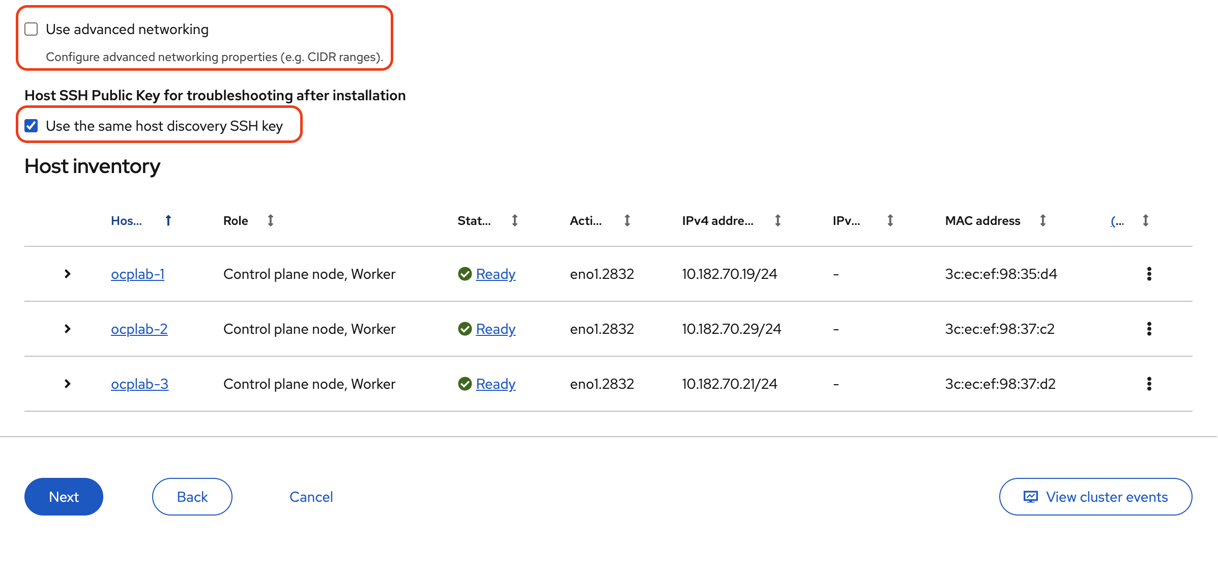
Leave the Use advanced networking option unchecked. The default CIDRs for pods and services are fine unless you have a specific design in mind.
Finally, make sure the Host SSH Public Key for troubleshooting after installation is checked. Keeping it set to Use the same host discovery SSH key allows you to log in with SSH after installation, which is useful for quick checks or debugging.
Once all values are set and verified, click Next to continue to the review step.
#Step 9: Review and create
This page is a final safety check. We confirm what will be installed, then we launch it.
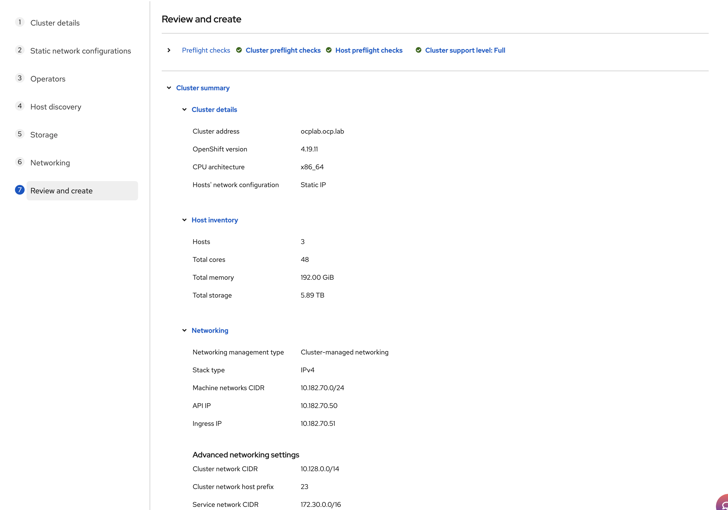
Scroll through Cluster details. Confirm that the cluster address and version are correct. Check the Host inventory count. You should see three hosts and the expected CPU, memory, and storage totals.
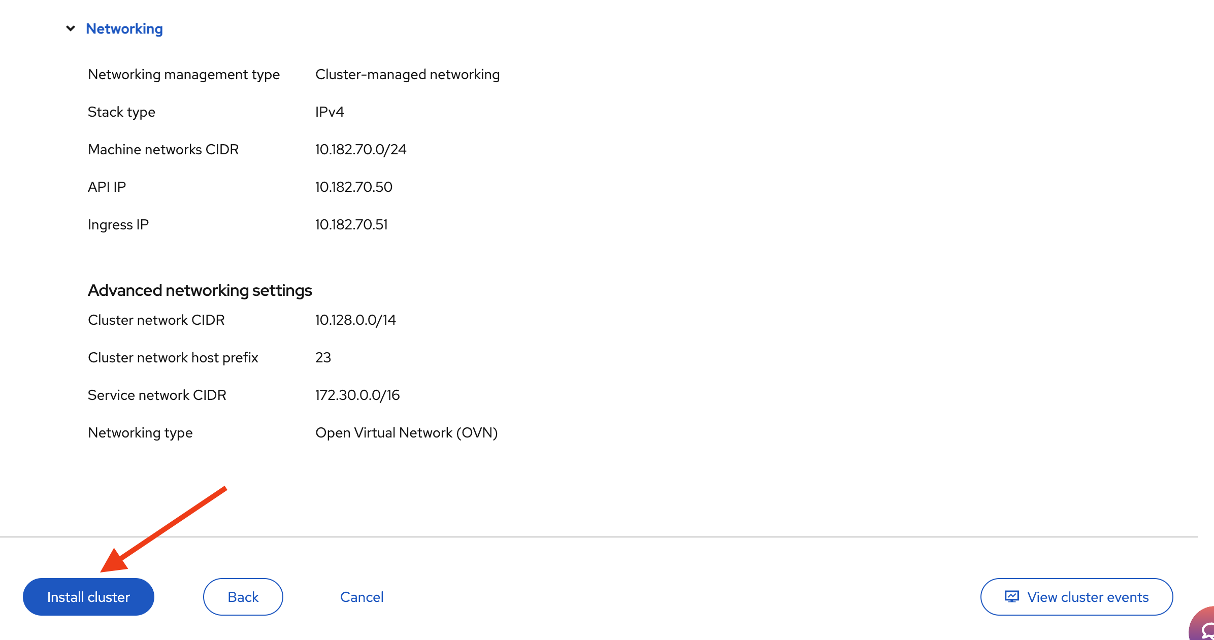
Expand the Networking section and read it line by line. The Machine network must match your VLAN subnet. The API IP and Ingress IP should be the exact values you picked in the Networking step, and they must be different from each other and from the node IPs.
If everything looks good, click Install cluster.
The installer will kick off. Nodes will reboot several times, and status will move through stages. This is normal; do not panic if a host shows “disconnected” for a short period.
Watch the progress bar and, when needed, click View cluster events for a live feed of what is happening.
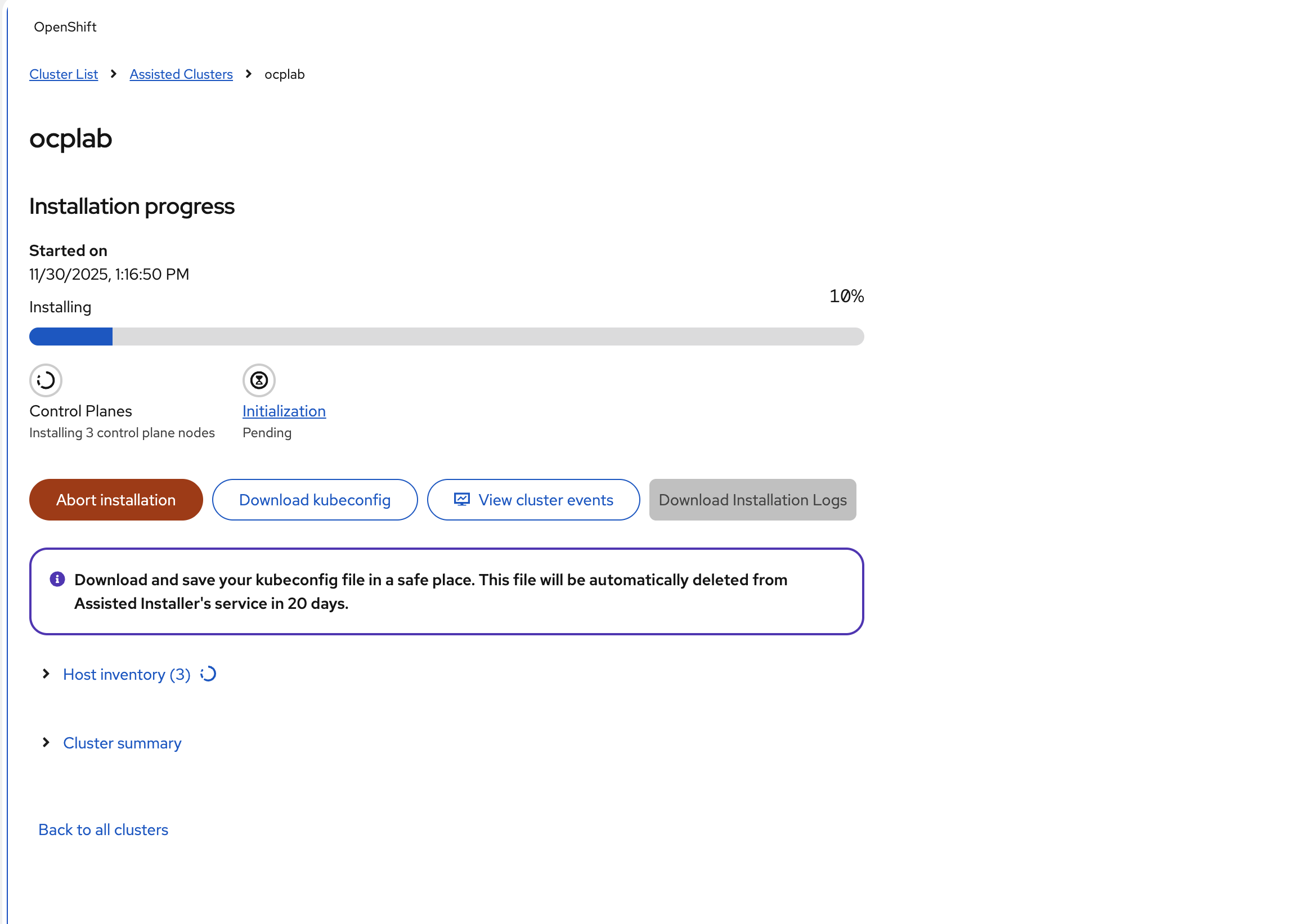
After 25 - 35 minutes, your cluster will be ready.
#Step 10: Post-installation
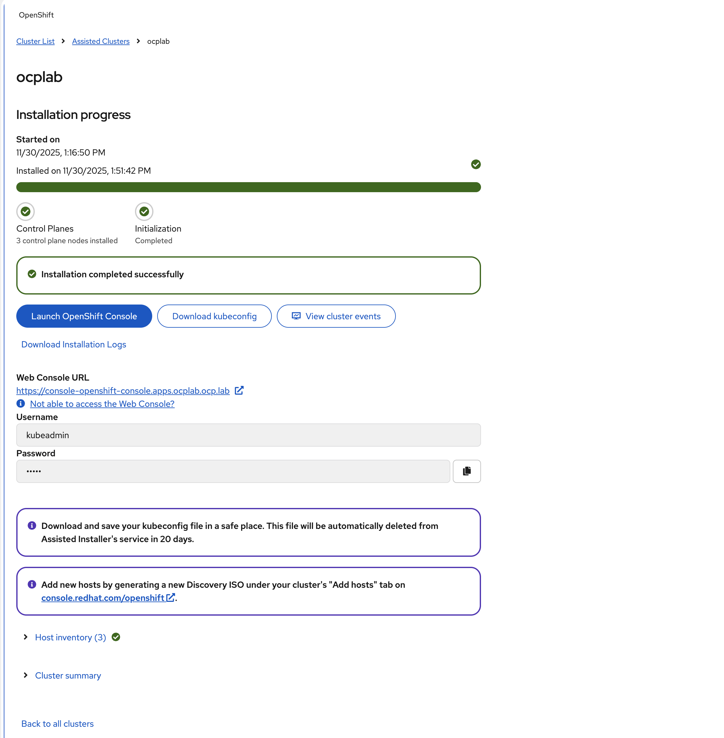
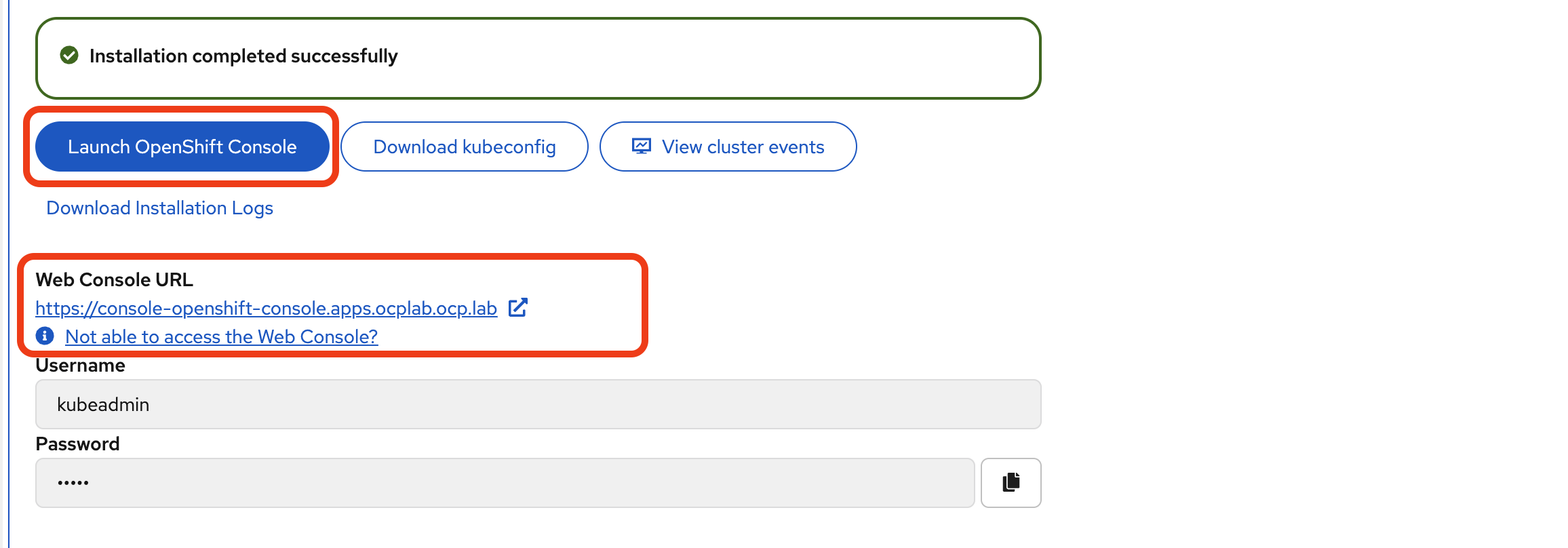
After the installation completes, the Assisted Installer displays a success message along with your cluster credentials and console URL. We need to download the credentials and verify that the cluster is accessible.
#Download the kubeconfig file
The kubeconfig file contains the credentials and connection details needed to interact with your cluster using the oc command-line tool.
In the Assisted Installer, click the Download kubeconfig button to download the file.
Save this file to your local computer. For this guide, we save it to ~/.kube/kubeconfig.
To use this configuration with the oc command-line tool, set it as your active kubeconfig:
export KUBECONFIG=~/.kube/kubeconfig
#Verify cluster nodes
Run the following command to check that all nodes are ready:
oc get nodes
You should see output similar to this:
OutputNAME       STATUS   ROLES                         AGE   VERSION
ocplab-1   Ready    control-plane,master,worker   41m   v1.32.7
ocplab-2   Ready    control-plane,master,worker   41m   v1.32.7
ocplab-3   Ready    control-plane,master,worker   24m   v1.32.7
All three nodes should show `STATUS` as `Ready`. If any node shows `NotReady`, wait a few more minutes for the cluster operators to finish initializing.
#Access the OpenShift web console
The Assisted Installer displays the Web Console URL and login credentials. The URL follows this format:
https://console-openshift-console.apps.ocplab.ocp.lab
Click Launch OpenShift Console or copy the URL and paste it into your browser.
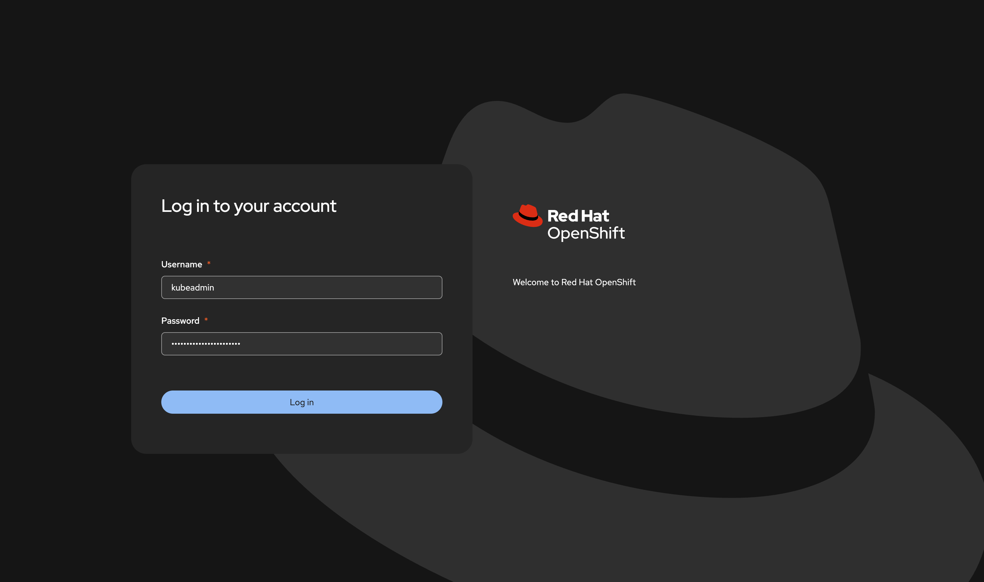
You may see a security warning because OpenShift uses a self-signed certificate by default. This is expected, proceed.
On the login page, enter the username `kubeadmin` and the password provided by the Assisted Installer.
After logging in, you should see the OpenShift dashboard.
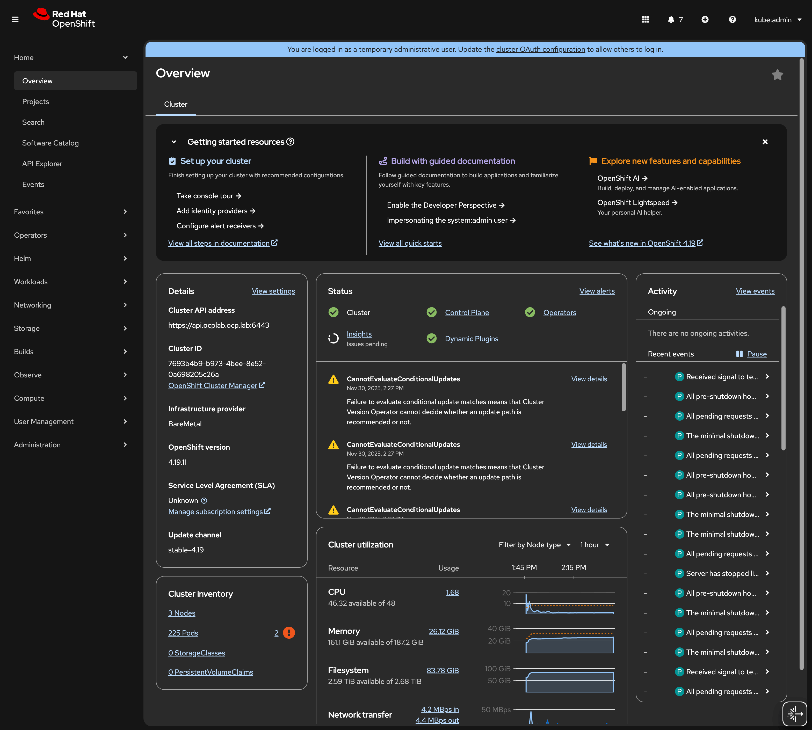
Your OpenShift cluster is now operational. You can begin deploying applications or exploring the platform through the Web Console or CLI.
#Conclusion
We have gone from provisioning servers, wiring up static networking, and walking through the Assisted Installer to validating the cluster with a few quick health checks.
This setup gives us a compact but highly available OpenShift control plane ready to run workloads. From here, the following steps are about shaping it to fit your needs: add worker nodes, install operators from the console, and hook it into your CI/CD pipeline or monitoring tools.
Remember to keep backups of your Kubeconfig and credentials. These small details can save you a lot of time when you need to log back in or recover access later.